Poly-pak piston seal installation -9, Rod assembly installation -9, Cylinder piston nut torque specifications -9 – JLG M4069 Service Manual User Manual
Page 81: Holding valve torque specifications -9
SECTION 4 - HYDRAULICS
3121639
– JLG Lift –
4-9
10. Install the bolts into the bushing using Loctite #242.
Refer to Cylinder Component Torque Specifications
Table for proper bolt torque values.
11. Remove the cylinder rod from the holding fixture.
12. Place new guidelock and hydrolock seals in the
applicable outside diameter grooves of both the pis-
ton and the cylinder head.
13. Position the cylinder barrel in a suitable holding fix-
ture.
EXTREME CARE SHOULD BE TAKEN WHEN INSTALLING THE
CYLINDER ROD, HEAD, AND PISTON. AVOID PULLING THE ROD
OFF-CENTER, WHICH COULD CAUSE DAMAGE TO THE PISTON
AND CYLINDER BARREL SURFACES.
14. With the barrel clamped securely, and while ade-
quately supporting the rod, insert the piston end into
the cylinder barrel. Ensure that the piston loading o-
ring and seal ring are not damaged or dislodged.
15. Continue pushing the rod into the barrel until the cyl-
inder head gland can be inserted into the cylinder
barrel.
16. Secure the cylinder head gland using the washer
ring and socket head bolts.
17. After the cylinder has been reassembled, the rod
should be pushed all the way in (fully retracted) prior
to the reinstallation of any holding valve or valves.
18. If applicable, install the cartridge-type holding valve
and fittings in the port block using new o-rings as
applicable.
WHEN REBUILDING THE LIFT CYLINDERS, APPLY LOCTITE 242
TO PISTON NUT AND SETSCREWS.
NOTE: These cylinders use setscrews which should be dis-
carded and replaced whenever they are removed.
19. Remove cylinder rod from the holding fixture.
20. Place new o-rings and seals in the applicable out-
side diameter grooves of both the piston and the cyl-
inder head.
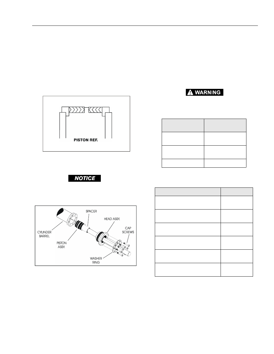
Figure 4-9. Poly-Pak Piston Seal Installation
Figure 4-10. Rod Assembly Installation
Table 4-2. Cylinder Piston Nut Torque Specifications
Description
Nut Torque Value
(Wet)
Lift Cylinder
(3369)
800 - 1000 ft lbs
(1120 - 1400 Nm)
LIft Cylinder
(4069)
1125 - 1375 ft lbs
(1575 - 1925 Nm)
Steer Cylinder
See Applicable Figure
Table 4-3. Holding Valve Torque Specifications
Description
Torque Value
Sun - 7/8 hex M20 x1.5 thds
30 - 35 ft lbs
(41 - 48 Nm)
Sun - 1-1/8 hex 1 - 14 UNS thds
45 - 50 ft lbs
(61 - 68 Nm)
Sun - 1-1/4 hex M36 x 2 thds
150 - 160 ft lbs
(204 - 207 Nm)
Racine - 1-1/8 hex 1-1/16 - 12 thds
50 - 55 ft lbs
(68 - 75 Nm)
Racine - 1-3/8 hex 1-3/16 - 12 thds
75 - 80 ft lbs
(102 - 109 Nm)
Racine - 1-7/8 hex 1-5/8 - 12 thds
100 - 110 ft lbs
(136 - 149 Nm)