Motor controller - modes of operation -4, Traction motor (drive) -4 pump motor (lift) -4, Features -4 – JLG M4069 Service Manual User Manual
Page 76: Traction mode -4, Cylinder checking procedures -4, Cylinder without counterbalance valves (steer) -4, Cutout heights -4, Pump motor (lift), 8 features traction mode, 9 cylinder checking procedures
SECTION 4 - HYDRAULICS
4-4
– JLG Lift –
3121639
4.7 MOTOR CONTROLLER - MODES OF
OPERATION
Traction Motor (Drive)
Drive in either forward or reverse will start only if the fol-
lowing conditions are satisfied:
1. Function switches off.
2. No procedure or diagnostic faults present.
3. Depress drive select. Lights indicating drive at the
platform control will flash. The controller must be
moved within 3 seconds after the drive select illumi-
nates.
4. FWD or REV selected as appropriate.
Once in “drive” mode, activating a function switch shall
not cause drive mode to be exited, the pump/traction con-
tactor drive shall not be energized it will be left at the trac-
tion position. If a function switch is selected during
traction, a procedure fault will occur when neutral is
selected, remaining until a function switch and both direc-
tions are no longer selected.
When the controller is returned to neutral, the controller
will control smooth stopping of the machine, using plug
braking, before the brake is allowed to operate.
NOTE: Depressing the lift function switch while driving will
not interrupt drive function.
Pump Motor (LIft)
Pump motor drive will start only if the following conditions
are satisfied:
1. Accelerator in neutral position.
2. Traction mode off (brake applied).
3. Depress lift select. the lights indicating lift select at
the platform control will flash. The accelerator must
be moved within 3 seconds after the lift light illumi-
nates.
NOTE: Depressing the drive function switch while lifting will
not interrupt lift function.
Any time brushes are being replaced in a drive
motor or pump motor, all brushes in the motor
should be replaced.
4.8 FEATURES
Traction Mode
NOTE: The lift up and drive functions are proportional.
The drive function is fully proportional with automatic
speed cutback above elevation. The system is designed
for maximum traction to be delivered to both wheels at all
times.
Machines equipped with oscillating axle will have oscilla-
tion below elevation cutback speed only.
4.9 CYLINDER CHECKING PROCEDURES
NOTE: Cylinder checks must be performed any time a cylin-
der component is replaced or when improper system
operation is suspected.
Cylinder Without Counterbalance Valves
(Steer)
1. Using all applicable safety precautions, activate
hydraulic system and fully extend cylinder to be
checked. Shut down hydraulic system.
2. Carefully disconnect hydraulic hose from retract port
of cylinder. There will be initial weeping of hydraulic
fluid which can be caught in a suitable container.
After initial discharge, there should be no further
leakage from the retract port.
3. Activate hydraulic system, and activate cylinder
extend function.
4. If cylinder retract port leakage is less than 6-8 drops
per minute, carefully reconnect hose to retract port
and retract cylinder. If leakage continues at a rate of
6-8 drops per minute or more, cylinder repairs must
be made.
5. With cylinder fully retracted, shut down motor and
carefully disconnect hydraulic hose from cylinder
extend port.
6. Activate hydraulic system and activate cylinder
retract function. Check extend port for leakage.
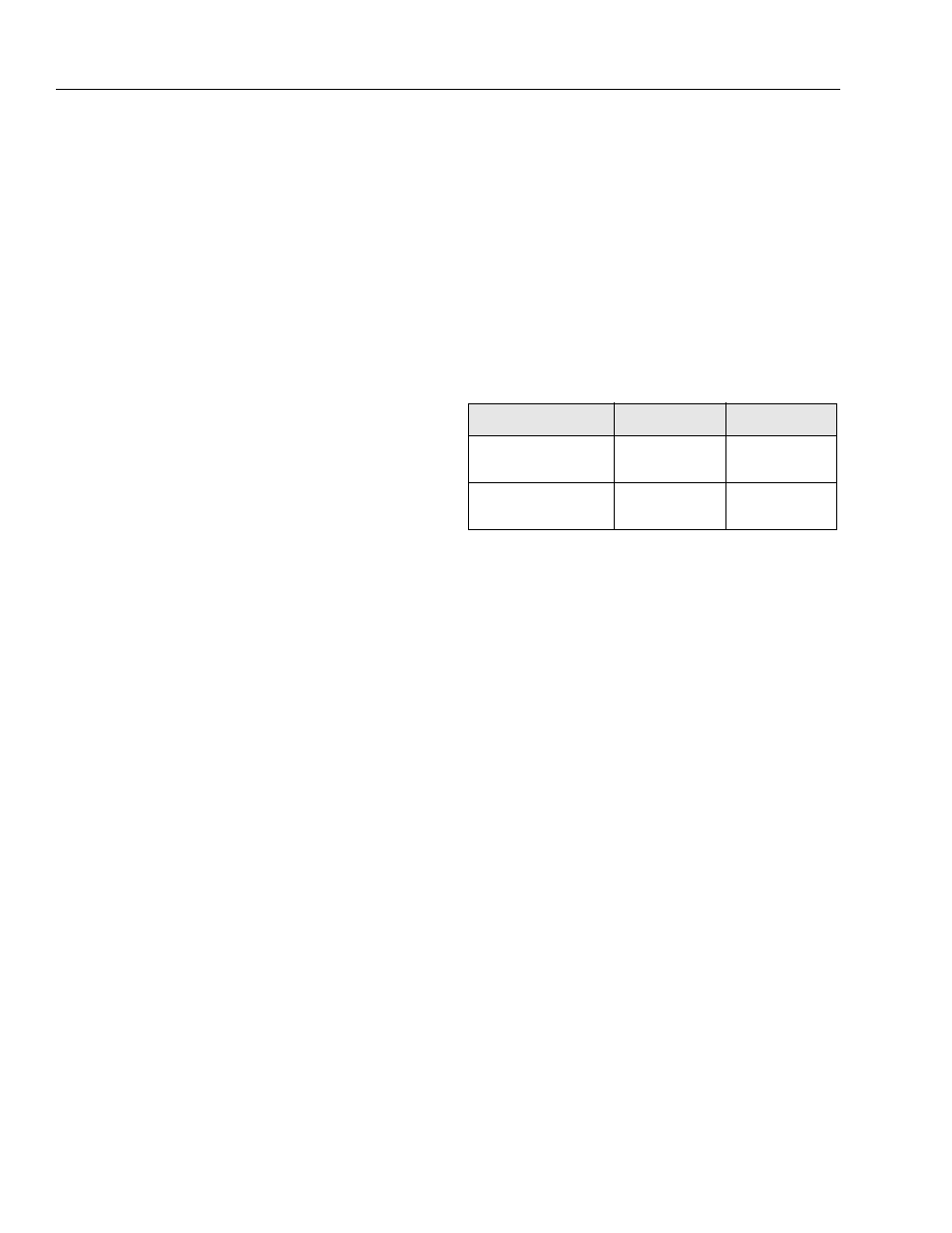
Table 4-1. Cutout Heights
Function
M3369/3369LE
M4069/4069LE
Elevated Cutback Height
8 ft - 9 ft 6 in
(2.4 m - 2.9 m)
9 ft 6 in - 11 ft 8 in
(2.9m - 3.6m)
Drive Cutout Height
N/A
28 ft - 30 ft
(8.5 m - 9.1m)