Cover sub-assembly -38, Cover sub-assembly – JLG M4069 Service Manual User Manual
Page 70
SECTION 3 - CHASSIS & SCISSOR ARMS
3-38
– JLG Lift –
3121639
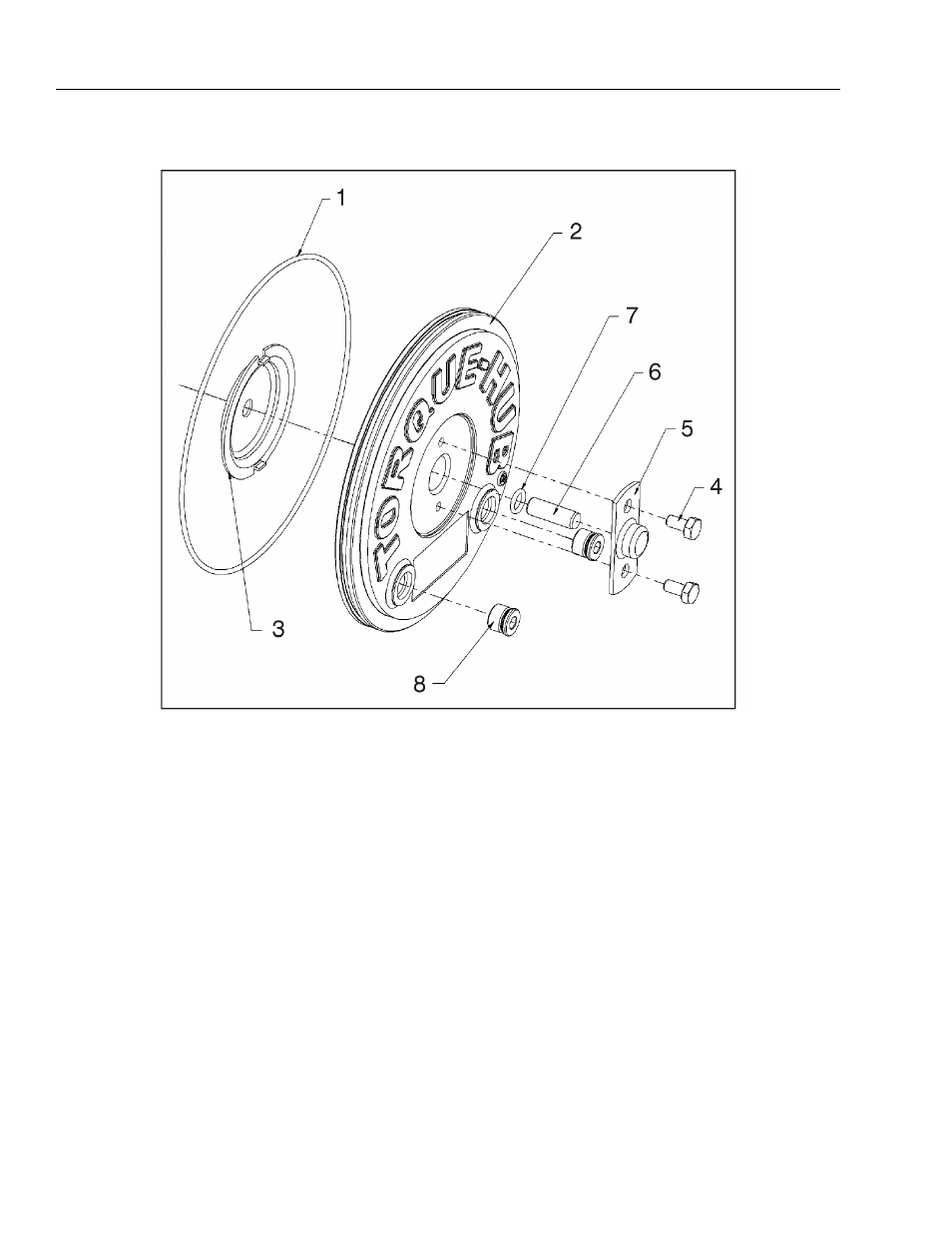
Cover Sub-Assembly
1. Grease O-Ring (7) and insert groove in Cover (2).
2. Assemble Disengage Cap (5) onto Cover using two
Hex Head Bolts (4). Torque bolts to 70-80 in-lbs.
3. Insert Disengage Rod (6) into hole in Cover until it
touches the inside of the Disengage Cap.
NOTE: The Disengage Rod can be inserted either end first.
4. Grease the face of the Thrust Washer (3) and place
in the Cover making sure the tangs on the Washer
seat into the pockets in the Cover.
5. Install the O-ring Pipe Plugs (8) into the Cover. The
plugs should be hand tight according to SAE stan-
dard.
1. O-Ring
2. Cover
3. Thrust Washer
4. Hex Head Bolts
5. Disengage Cap
6. Disengage Rod
7. O-ring
8. O-ring Pipe Plugs
Figure 3-25. Cover Sub-Assembly