3 machine operation, Inspect work area before operating lift, Interlock switch operating conditions – JLG 15VPSP Operator Manual User Manual
Page 37: Driving, Mast retracted, Bars raised, Not tilted), Engaged, Disengaged, Mast extended
SECTION 4 - MACHINE OPERATION
3120796
– JLG Lift –
4-3
4.3
MACHINE OPERATION
The following sequence of basic procedures must be fol-
lowed to safely operate the machine.
1.
At the ground control station, set power PLAT/OFF/
GRND key switch to the PLAT position to operate
from platform control, or GRND to operate from
ground controls. Note if equipped with optional Pro-
grammable Security Lock see Section 5 for instruc-
tions then return here to continue.
2.
Check that the EMERGENCY STOP button on the
GROUND and PLATFORM control are in the RESET
position for operation. Also check that Emergency/
Manual Decent Control valve is closed (lower access
opening in rear cover).
3.
Check the LED strip on the platform controller for
current battery charge level before operating lift to
be certain charge is sufficient to complete your work
task. If the battery charger is plugged into an AC
outlet, drive functions on the machine will be locked
out.
NOTE: If LED’S are flashing a fault code on the platform
control box at machine power-up, depress the
EMERGENCY STOP button and RESET it to clear any
false fault codes. If the fault continues after RESET,
see Section-3, “Troubleshooting” of the Service and
Maintenance Manual for information on reading fault
codes.
WORK AREA MUST BE A SMOOTH, FIRM AND LEVEL SURFACE
FREE OF HOLES, LARGE CRACKS OR DEBRIS ON SURFACE. THE
WORK SURFACE MUST BE CAPABLE OF SUPPORTING THE WEIGHT
OF THE MACHINE PLUS THE PLATFORM’S MAXIMUM RATED LOAD
CAPACITY. ALWAYS CHECK THE BUBBLE LEVEL INDICATOR ON
BASE FRAME TO BE SURE MACHINE IS LEVEL BEFORE RAISING
PLATFORM.
4.
Inspect work area before operating lift.
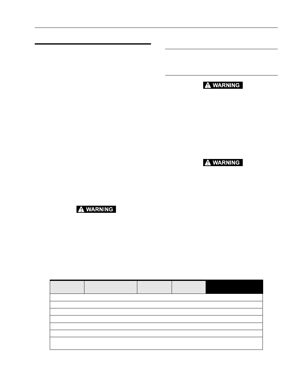
Interlock Switch Operating Conditions
Table 4-1. shown, lists machine response to various inter-
lock switch positions.
Driving
WHEN DRIVING WITH PLATFORM LOWERED, DO NOT ATTEMPT TO
DRIVE MACHINE UP A RAMP (GRADE) OF GREATER THAN TEN
(10%) PERCENT, AS TIPPING COULD OCCUR.
NEVER ATTEMPT TO DRIVE ONTO A GRADE WITH THE PLATFORM
ELEVATED.
1.
Enter platform and close the front platform gate if the
platform is configured as a closed platform. If plat-
form is configured as open, enter rear of platform
and close the mid platform gate before driving. (See
Figure 4-1.)
FALL PROTECTION EQUIPMENT MUST BE WORN AND ATTACHED
TO THE LANYARD ATTACHMENT AT ALL TIMES WHILE OPERATING
THIS MACHINE. FAILURE TO FOLLOW THESE INSTRUCTIONS
COULD RESULT IN DEATH OR SERIOUS INJURY.
2.
Attach your fall protection harness to the lanyard
attachment on the top platform rail at the rear of the
platform.
3.
Check the floor and overhead area in the direction of
travel for obstacles to avoid.
4.
Press and HOLD the DRIVE ENABLE button on the
JOYSTICK then gently point the JOYSTICK in the
direction of travel. If necessary, adjust the VARIABLE
SPEED CONTROL knob on the controller (round
knurled knob) while driving.
Table 4-1.
Machine Interlock Switch Operating Conditions.
Elevation/
Speed Switch
Drive Cutout
(PHP System)
Tilt Status
Brake Status
Controller Response
mast retracted
bars raised
(not tilted)
engaged
Full Drive and Lift
mast retracted
bars raised
(not tilted)
disengaged
Drive and Lift disabled
mast extended
bars lowered
(not tilted)
engaged
Drive 25% max.
mast extended
bars lowered
(tilt)
engaged
Drive and Lift disabled
mast retracted
bars raised
(tilt)
engaged
Lift disabled
mast retracted
bars raised
(tilt)
disengaged
Drive and Lift disabled
mast retracted
bars raised/battery charger
plugged-in
(not tilted)
engaged
Drive disabled