JLG 110HX ANSI Service Manual User Manual
Page 97
SECTION 2 - PROCEDURES
3120636
– JLG Lift –
2-73
Inspection
1.
Clean all parts thoroughly.
2.
Closely inspect all parts for excessive wear, cracks
and chips. Replace parts as necessary.
3.
Discard seals and o-rings.
4.
Closely inspect bearings and bearing contact sur-
faces. Replace as necessary.
NOTE: Bearings may be reused if, after thorough inspection,
they are inspection, they are found to be in good
condition.
Assembly
NOTE: Lubricate all seals and o-rings with clean hydraulic
oil prior to assembly.
1.
Press new rotary seal (1) into housing (7). Note the
direction of seal.
2.
Install new bearing (2) on shaft (4).
3.
Install shaft assembly and retaining ring (3) into
housing (7).
4.
Install dowel pins (17), spring retainer (16), and
springs (5 & 6) into housing (7).
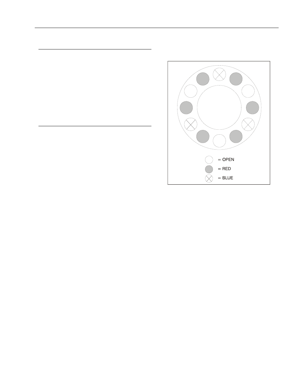
NOTE: Be sure to use the same number of springs and
spring pattern as recorded during disassembly.
5.
Position new large diameter return plate (8) in hous-
ing with tabs guided by dowel pins (17) until disc
rests on springs (5 & 6).
NOTE: Discs (8 & 23) and friction discs (22) should remain
dry during installation. No oil contaminate disc sur-
faces.
6.
Place new disc (22) on shaft (4) until it contacts
return plate (8).
7.
Add additional discs (23) as required to complete
assembly.
8.
Insert separators (10) in holes of return plate (8).
9.
Install new o-ring (19), new back-up ring (18), new o-
ring (20) and new back-up ring (21) on piston (24).
Insert piston (24) into end cover (13) being careful
not to shear o-rings or back-up rings.
10.
Install new case seal (11) in housing (7) then install
bleeder screw (14) in end cover.
11.
Position end cover (13) on housing (7) aligning
dowel pins (17) with holes in end cover.
12.
Insert capscrews (12) and tighten evenly to draw
end cover (13) to housing (7). Torque capscrews to
55 ft. lbs. (75 Nm).
Figure 2-30. Spring Loading