JLG 110HX ANSI Service Manual User Manual
Page 102
SECTION 2 - PROCEDURES
2-78
– JLG Lift –
3120636
4.
\Operational Check.
a. With no load in the platform, raise the boom
completely and fully extend the boom.
b. Engage auxiliary power.
c. Engage LIFT DOWN until the blue light turns off
and the yellow light turns on. When the yellow
light turns on, shut down the machine and check
the boom angle. The boom angle should be 63-
67 degrees. If the boom angle is within this
range, proceed to step 4. If the boom angle is
not within this range, contact the JLG Service
Department for further assistance.
Engage LIFT DOWN until the blue light turns off
and the red light turns on. When the red light
turns on, shut down the machine and check the
boom angle. The boom angle should be 55-58
degrees. If the boom angle is within this range,
the boom length/angle indicating system is
working properly and requires no further adjust-
ment. If the boom angle is not within this range,
contact the JLG Service Department for further
assistance.
d. Engage LIFT DOWN. The boom function should
stop at 41 degrees or a higher angle. If the boom
does not stop at 41 degrees, contact the JLG
Service Department.
100HX+10
1.
Length Indicator Adjustment.
a. Fully retract the boom and place it in the 0 (+3/-
0) degrees horizontal position.
b. With the engine running, check test point 10
(TP10). Adjust trimpot 5 (P5) until 10 Volts is
obtained on TP10.
c. Set TP1 on the load radius circuit card to 1.8
Volts by adjusting P1.
d. Loosen the Allen screws which anchor the tim-
ing belt pulley (1st generation) or timing gear
(2nd generation) to the shaft of the 5K pot. On
3rd generation sensor boxes, loosen the three
screws holding the pot in place. This enables
the pot/pot shaft to move freely.
e. Turn the ignition switch on. Adjust the 5K pot/pot
shaft until the proper voltage appears at TP2 on
the load radius circuit card and also at the green
wire on the 5K pot. (See Table 2-5 for proper
voltage.)
f. Tighten the Allen screws on the timing belt pul-
ley/timing gear or tighten the three screws, as
applicable.
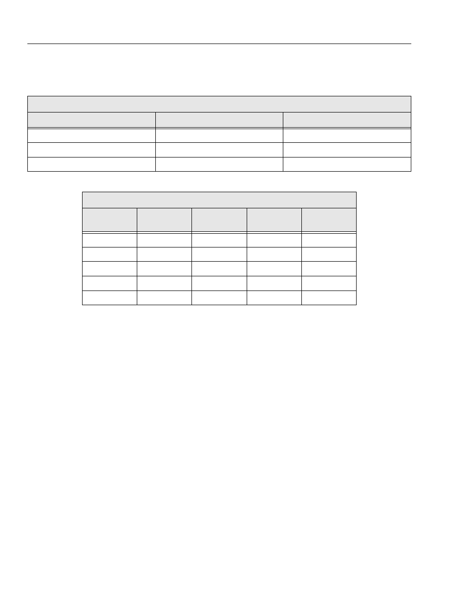
Table 2-5.Card Adjustment - 1st and 2nd Generation
Boom Radius Use Procedure
Model
Length Indicator
Boom Angle Sensor
100HX
2.5 Volts
0.18 Volts
110HX
2.0 Volts
0.20 Volts
100HX+10
2.5 Volts
0.18 Volts
Table 2-6.Card Adjustment - 3rd Generation
Boom Radius Use Procedure
Adjustment
Location
100HX
Dual Capacity
110HX
Single Capacity
110HX
Dual Capacity
100HX+10
Single Capacity
P1
1.114 Volts
1.151 Volts
1.151 Volts
1.018 Volts
P2
1.585 Volts
2.548 Volts
2.128 Volts
2.577 Volts
P3
1.959 Volts
5.0 Volts
2.548 Volts
5.0 Volts
P4
0.05 Volts
0.05 Volts
0.05 Volts
0.05 Volts
P5
1610 Ohms
1340Ohms
1340 Ohms
1000 Ohms