5 use of the capacity chart, Capacity indicator locations, Use of the capacity chart -5 – JLG 4017RS Operator Manual User Manual
Page 85: Capacity indicator locations -5
Section 5 - Attachments
5-5
31200938
5.5
USE OF THE CAPACITY CHART
To properly use the capacity chart (see page 5-6), the operator must first determine and/
or have the following:
1. An approved attachment. See “Approved Attachments” on page 5-1.
2. The proper Capacity Chart.
3. Weight of the load being lifted.
4. Load placement information:
a. HEIGHT where the load is to be placed.
b. DISTANCE from the front tires of the telehandler where the load is to be placed.
5. On the capacity chart, find the line for the height and follow it over to the distance.
6. The number in the load zone where the two cross is the maximum capacity for this
lift. If the two cross at a division between zones, the smaller number must be used.
The number in the load zone must be equal to or greater than the weight of the load to be
lifted. Determine the limits of the load zone on the capacity chart and keep within these
limits.
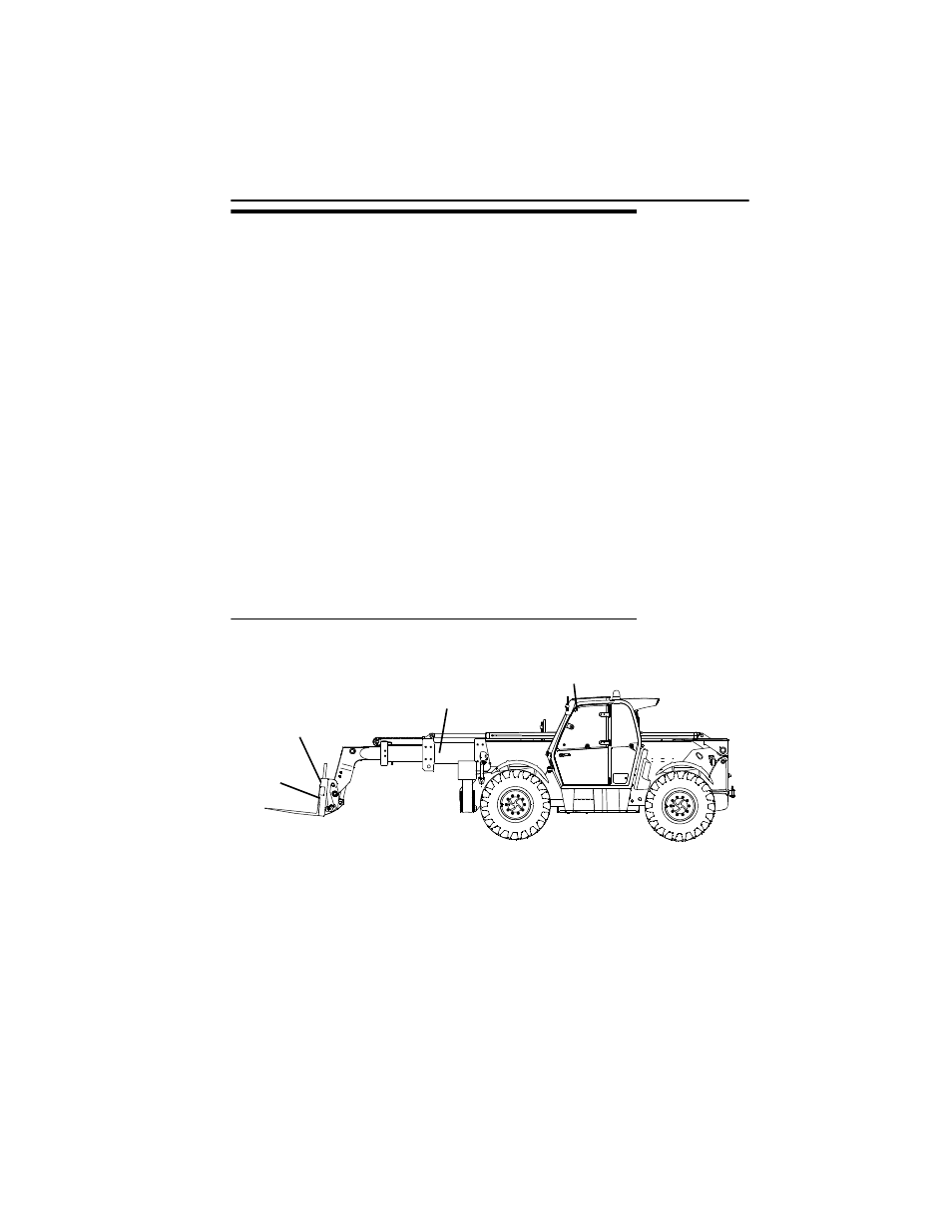
Capacity Indicator Locations
A
OAM3830
BOOM
EXTENSION
INDICATOR
FORK
WEIGHT
STAMP
ATTACHMENT
IDENTIFICATION
PLATE
BOOM ANGLE
INDICATOR
(INSIDE CAB)