Example, Example -8 – JLG 4017RS Operator Manual User Manual
Page 88
Section 5 - Attachments
5-8
31200938
Example
A contractor owns a model xxxx telehandler with a fork carriage. He knows this
attachment may be used with his model since:
• The attachment style, weight, dimensions and load center match the attachment data
on the capacity chart.
• The capacity chart is clearly marked for model xxxx and corresponds with machine
configuration being used.
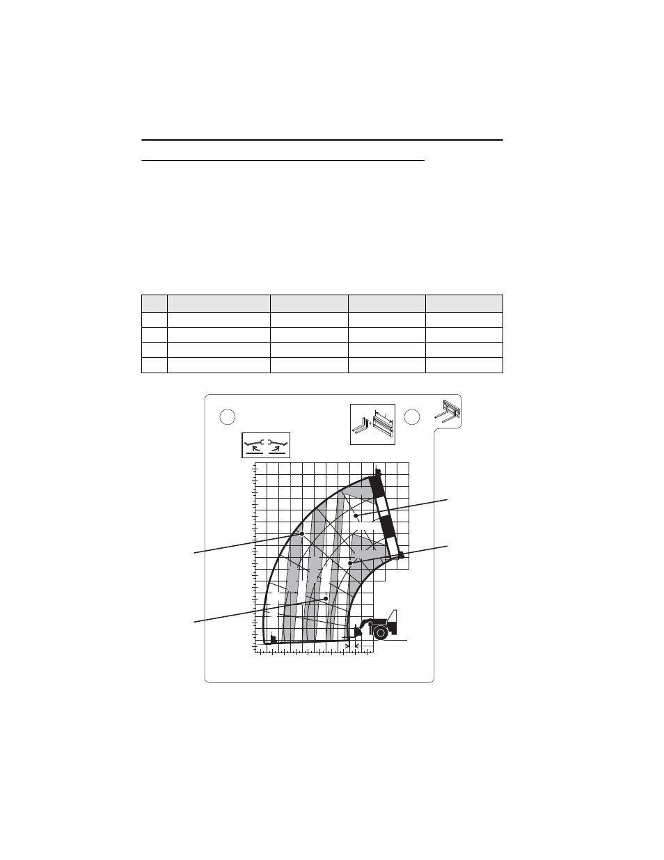
Below are examples with various conditions the contractor may encounter and whether
or not the load may be lifted.
Note: This is a sample capacity chart only! DO NOT use this chart, use the one located in your
operator cab.
Load Weight
Distance
Height
OK to Lift
1
1250 kg (2755 lb)
4,0 m (13.1 ft)
3,5 m (11.5 ft)
Yes
2
750 kg (1653 lb)
6,0 m (19.7 ft)
9,0 m (29.5 ft)
NO
3
2500 kg (5512 lb)
2,0 m (6.6 ft)
6,5 m (21.3 ft)
Yes
4
3000 kg (6614 lb)
1,5 m (4.9 ft)
10,5 m (34.4 ft)
NO
OAM1921
XXX kg MAX
-
XXX mm
XXX mm
XXXX
XXXX XXXX
8m
9m
10m
11m
12m
13m
14m
o
10
o
20
o
30
o
40
o
50
o
60
o
75
o
0
0m
-1m
1m
2m
3m
4m
5m
6m
7m
0m
1m
2m
3m
4m
5m
9m 8m 7m 6m
XXX mm
350kg
500kg
750kg
1000kg
1500kg
2000kg
2500kg
3700kg
A
B
C
D
Example 1
Example 3
Example 2
Example 4