Installation, Installation -11 – JLG 680S Service Manual User Manual
Page 205
SECTION 4 - BOOM & PLATFORM
3121234
– JLG Lift –
4-11
18. Secure the sling and lifting device at the telescope
cylinder’s approximate center of gravity, and lift the
cylinder to the aft end of the boom assembly.
WHEN INSERTING THE TELESCOPE CYLINDER INTO THE BOOM,
IT MAY BE NECESSARY AT SOME POINT TO TURN THE CYLIN-
DER SLIGHTLY IN ORDER TO CLEAR ASSEMBLIES MOUNTED
WITHIN THE BOOM. CARE MUST BE TAKEN TO MOVE THE CYL-
INDER SLOWLY INTO POSITION. DAMAGE TO COMPONENTS
MAY RESULT FROM FORCIBLE IMPACT WITH THESE ASSEM-
BLIES.
19. Align the cylinder with the slots at aft end of mid
boom section, then secure cylinder with mounting
hardware.
20. Align holes in aft end of the fly boom section with
holes in wire rope mounting block, then secure with
mounting hardware.
21. Align holes in aft end of the mid boom section with
holes in wire rope mounting block, then secure with
mounting hardware.
NOTE: Boom wire ropes must be torqued after installation of
the boom assembly.
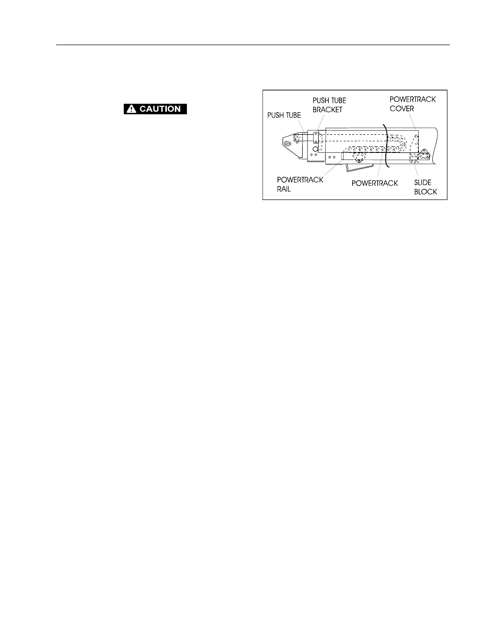
22. Install the hydraulic lines and electrical cables, and
the harnessing powertrack components as follows:
a. Align holes in powertrack rail with attachment
holes in side of the base boom section. Secure
the rail with mounting hardware.
b. Install powertrack to rail with mounting hard-
ware.
c. Attach push tube bracket to the side of the mid
boom section with mounting hardware.
NOTE: Do not over tighten attach bolt on push tube bracket.
It should pivot freely.
d. Install slide block and wear pads to the pow-
ertrack rail with mounting hardware.
e. Install powertrack to push tube with mounting
hardware.
f. Carefully feed the hoses and electrical cables
through the aft end of the powertrack rail, pow-
ertrack and push tube.
g. Ensure all hoses and cables are properly routed
through the powertrack rail, powertrack and
push tube. Tighten or install all clamping or
securing apparatus to the hoses or cables, as
necessary.
h. Install powertrack cover and push tube rods with
mounting hardware.
Installation
1. Using a suitable lifting device, position boom
assembly on upright so that the pivot holes in both
boom and upright are aligned.
2. Install boom pivot pin, ensuring that location of hole
in pin is aligned with attach point on upright.
3. If necessary, gently tap pin into position with soft
headed mallet. Secure pin mounting hardware.
4. If necessary, gently tap pin into position with soft
headed mallet. Secure pin mounting hardware.
5. Connect all wiring to the ground control box.
6. Connect all hydraulic lines running along side of
boom assembly.
7. Using all applicable safety precautions, operate lift-
ing device in order to position boom lift cylinder so
that holes in the cylinder rod end and boom struc-
ture are aligned. Insert the lift cylinder pin, ensuring
that location of hole in pin is aligned with attach
point on boom.
8. Align holes in boom structure with hole in master
cylinder. Insert the master cylinder pin, ensuring that
location of hole in pin is aligned with attach point on
boom.
9. Adjust retract and extend cables to the proper
torque. Refer to Section 4.4, Boom Rope Torquing
Procedures.
10. Using all applicable safety precautions, operate
machine systems and raise and extend boom fully,
noting the performance of the extension cycle.
11. Retract and lower boom, noting the performance of
the retraction cycle.
Figure 4-11. Reassembly of Components - Boom
Powertrack Assembly