13 procedure for setting gear backlash, Procedure for setting gear backlash -89 – JLG 680S Service Manual User Manual
Page 137
SECTION 3 - CHASSIS & TURNTABLE
3121234
– JLG Lift –
3-89
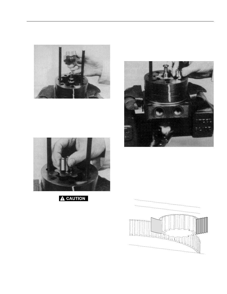
3. Assemble the rotor (8A), counterbore down if appli-
cable, into stator (8B), and onto wear plate (9) with
rotor splines into mesh with drive link (10) splines.
NOTE: If the manifold side of the rotor was etched during
Torqlink disassembly, this side should be up. If the
rotor is not etched and does not have a counterbore,
use the drive link spline contact pattern apparent on
the rotor splines to determine the rotor side that must
be against the wear plate.
4. Assemble six vanes (8C), or as many vanes that will
readily assemble into the stator vane pockets.
EXCESSIVE FORCE USED TO PUSH THE ROTOR VANES INTO
PLACE COULD SHEAR OFF THE COATING APPLIED TO THE STA-
TOR VANE POCKETS.
5. Grasp the output end of coupling shaft (12) with
locking pliers or other appropriate turning device
and rotate coupling shaft, drive link and rotor to seat
the rotor and the assembled vanes (8C) into stator
(8B), creating the necessary clearance to assemble
the seventh or full complement of seven vanes.
Assemble the seven vanes using minimum force.
6. Remove the two assembled bolts (1) if used to retain
stator and wear plate.
3.13 PROCEDURE FOR SETTING GEAR
BACKLASH
1. Set backlash to 0.008 to 0.012" (0.203 to 0.304 mm)
using the following procedure.
2. Place shim (JLG p/n 4071009) between pinion and
bearing on the bearing high spot.