10 coupler assembly (s/n 0030002099 to present), Engaging manual lockout lever, Servicing the breakaway assembly – JLG T500J Service Manual User Manual
Page 63: Coupler assembly (s/n 0030002099 to present) -27
SECTION 3 - CHASSIS & TURNTABLE
3121200
– JLG Lift –
3-27
3.10 COUPLER ASSEMBLY (S/N
0030002099 TO PRESENT)
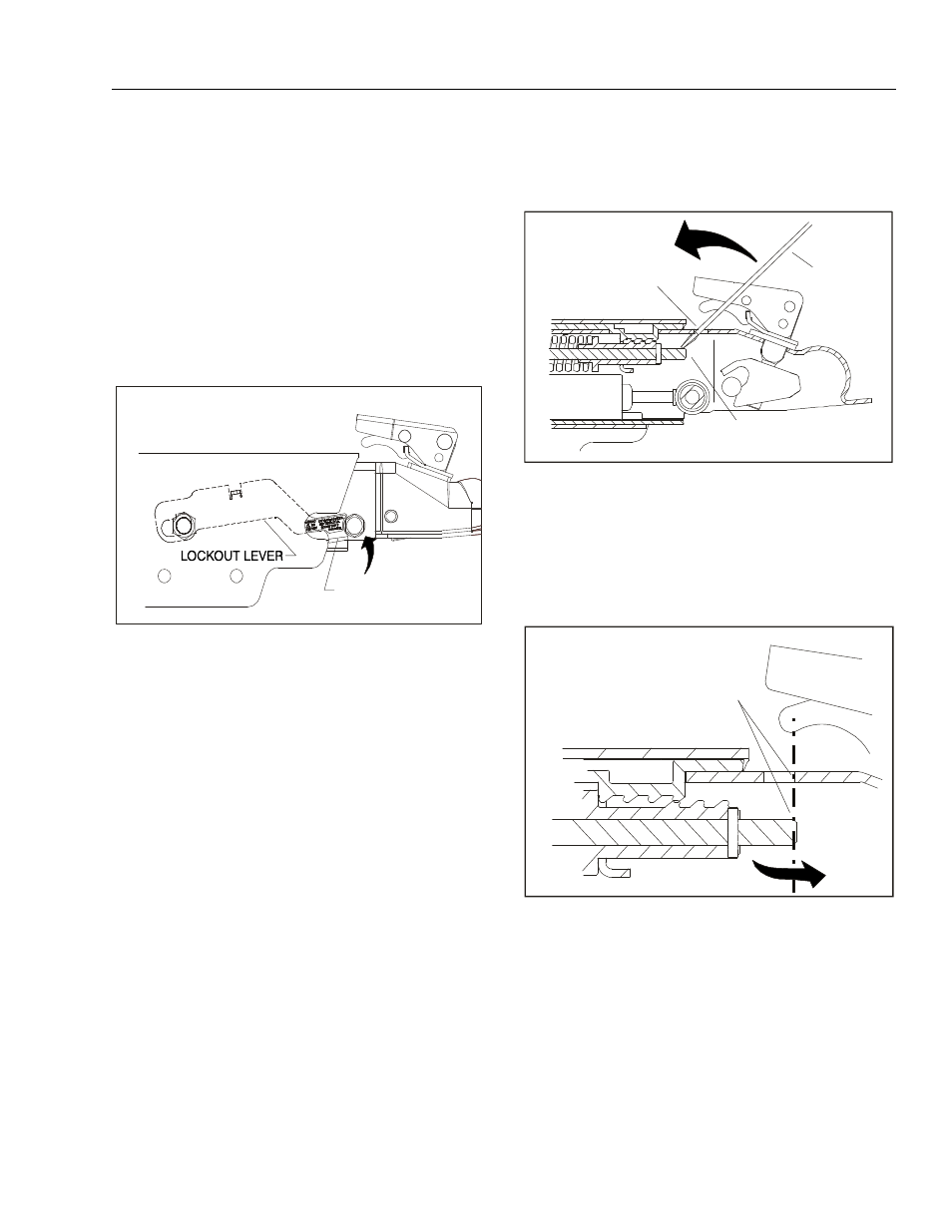
Engaging Manual Lockout Lever
The manual lockout lever is used to control the brake
pressure being applied to the trailer when backing up.
Having the actuator in the extended position will make it
easier to engage the lockout lever. To engage the lockout
lever, move the lever back and upwards until the front of
the lever nests into the round spacer as shown below.
This will prohibit movement of the actuator when backing
up. The lockout lever will move to the towing position
when you drive forward again.
Servicing the Breakaway Assembly
A thorough inspection of the breakaway assembly is
required if it is applied at any time. Damaged parts must
be replaced. If there is any damage to the lanyard itself
the entire pushrod assembly will need to be replaced.
To disengage the breakaway mechanism, first release the
brake line pressure by briefly opening a bleeder valve.
Extend the coupler forward to gain access to the 1/2" hole
on the top of the coupler housing as shown below.
Insert a flat head screwdriver into the access hole and
push down on the pushrod assembly and pivot the push-
rod towards the front of the coupler. Make sure the push-
rod assembly is moved to its furthermost forward position
(towards the front of the coupler) by pushing down and
forward on the rod. Inspect and replace parts as needed.
NOTE: The end of the pushrod should line up with the front
of the 1/2" access hole.
DO NOT TOW IF LOCK-OUT
LEVER IS ENGAGED
LIFT LEVER TAB TO
ENGAGE LOCKOUT
ACCESS HOLE
SCREWDRIVER
PUSHROD MUST BE
COMPLETELY FORWARD
PUSHROD MUST BE
COMPLETELY FORWARD
(END OF PUSHROD SHOULD BE
IN LINE WITH FRONT OF
ACCESS HOLE)