Sample capacity chart, Sample capacity chart -2, Warning – JLG 4009 Suspended Load Supplement Operator Manual User Manual
Page 38
Section 4 - Attachments
4-2
31200487
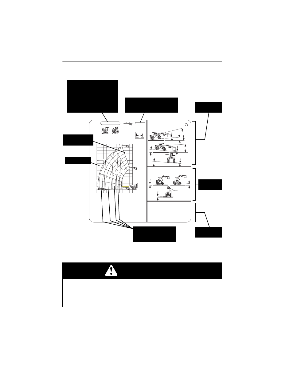
Sample Capacity Chart
Note: This is a sample capacity chart only! DO NOT use this chart, use the one
located in your operator cab.
WARNING
TIP OVER HAZARD. All loads shown on rated capacity chart are based on
machine being operated within the parameters indicated on the appropriate
capacity chart; proper size tires being properly inflated; and the telehandler being
in good operating condition. Failure to comply could result in death or serious
injury.
OAM2331
TRAVELLING (PICK & CARRY)
REQUIRES LOAD ON HOOK.
MAX TRAVEL WITH RATED LOAD XX M/S.
(WALKING SPEED).
BOOM FULLY RETRACTED.
MAX BOOM
ANGLE XX°
KEEP TRUSS BOOM HORIZONTAL
WITHIN ±XX DEGREES.
P/N XXXXXXXX
LIFTING (STATIONARY)
REQUIRES FIRM SURFACE WITH LOAD ON HOOK.
LEVEL CHASSIS BEFORE LIFTING.
JIB LEVEL WITHIN ±XX°.
TRUSS BOOM
±XX° MAX
XXXXXXXXXX A
XXXX
SPECIFICATIONS FOR SAFE USE
1. TYRE SIZES:
- XXX/XX-XX XXPLY XX PSI / X BAR.
2. IN-SERVICE WIND SPEED:
- XXM/S (XXKM/H).
3. GROUND CONDITIONS:
- FIRM SURFACES FOR LIFTING.
- SLOPE AND LOAD LISTED ABOVE FOR
BOTH CONFIGURATIONS.
4. STANDARD USED: (AS 1418.19-2007).
XX
0°
10°
20°
30°
40°
50°
60°
70°
A
B
C
D
E
F
G
m
XX
XX
kg
XX
XX
kg
XX
XX
kg
XX
Xk
g
XX
Xk
g
XX
XX
XX
XX
XX
XX
XX
XX
XX
XX
XX
XX
XX
XX
XX
XX
XX
XX
XX
XX
XX
XX
XX
XX
XX
XX
XXXMM
MAX
XX° MAX
MAX BOOM
ANGLE XX°
XX° MAX
XXXMM
MAX
MAX BOOM
ANGLE XX°
XX° MAX
XXXMM
MAX
X° MAX
X° MAX
X° MAX
Boom Extension
Indicator (arc)
Load zones indicate
the maximum weight
that may be safely lifted.
These numbers must match the
model/option number stamped
on the attachment ID Plate.
Boom Angle
This Capacity Chart may be
used with this model ONLY.
The model of your
telehandler is indicated on
the boom or chassis.
Model XXXX is used for
demonstration purposes only.
Travelling
Information
Specifications
for Safe Use
Lifting
Information