Caution – Snorkel TB85J Fixed Axle CE User Manual
Page 53
Chapter 8 – Operation
TB80/TB85J Fixed Axle – 0112823EE
49
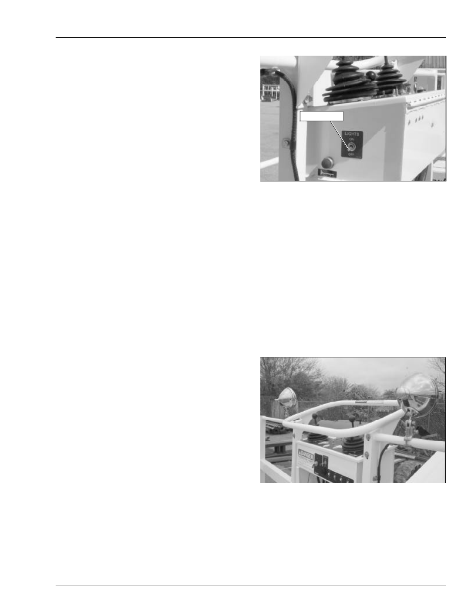
Figure 8.9 – Upper Controls
If the engine is running, the idle speed increases when
the driving lights are turned on.
Note
Working with the driving or platform work lights on, while
the engine is off, can discharge the batteries enough
that the engine will not start or the emergency power sys-
tem will not operate. If the engine cannot be left running
while the lights are on, start and run the engine for at
least 15 minutes each hour.
Platform Work Lights
The optional platform work lights are located on the top
rail of the platform next to the upper controls (refer to
Figure 8.10). The direction a light points can be adjusted
by using two
1
/
2
″
wrenches to loosen the clamp below the
light.
Figure 8.10 – Upper Controls
The lights are operational when the machine is set up for
operation from the upper controls.
the LPG gas tank if using LPG. Always keep the LPG
tank shut-off valve closed when not using LPG.
To switch from gasoline to LPG with the engine running:
1. Open the shut-off valve on the LPG tank.
2. Place the fuel switch in the LPG position.
To switch from LPG to gasoline with the engine running:
1. Place the fuel switch in the gasoline position.
2. Close the shut-off valve on the LPG tank.
Air Line
The optional air line may be used to conduct air for tool
operation at the platform. The input connector is at the
rear of the chassis and the output connector is at the
platform on the rotator guard. The maximum working pres-
sure of the line is 1,723 kPa (250 psi).
The air line may be used to conduct fluids such as water
or antifreeze. Contact Snorkel for compatibility informa-
tion before using the air line to conduct other fluids.
A
Caution
Fluid in the air line can damage some air tools or
freeze and damage the line. Drain and blow out the
air line after using it to conduct fluids.
Use the following procedure to drain the air line.
1. Close the input connector on the chassis.
2. Open the output connector at the platform.
3. Raise the boom slightly above horizontal.
4. Open the input connector on the chassis.
5. Allow the fluid to drain from the line.
6. Lower the boom and close both connections.
Driving Lights
The optional driving lights are for use in dimly lit areas
and are not intended for driving on public roadways. There
are two headlights at the front of the chassis and two
blinking taillights at the rear of the chassis.
The lights are operational when the machine is set up for
operation from the upper controls and the light switch
(refer to Figure 8.9) is turned on.
Light Switch