Snorkel SR3084SL User Manual
Page 26
Chapter 7 – Prestart Inspection
22
SR3084SL – 8210037
2. Remove the cap from the radiator (refer to Figure
7.2) and check the coolant level. If necessary, add
coolant.
Note
Refer to Chapter 2 for engine coolant specifi cations. The
need to regularly add fl uid indicates a leak that should
be corrected.
3. Tightly replace the cap.
Radiator
To inspect the radiator:
1. Inspect the radiator hoses and clamps for wear, leak-
age, or damage.
2. Make sure the hoses are not hardened, cracked, or
feel spongy.
3. Make sure the cap is in place and tight.
4. Check under the chassis for coolant that has leaked.
Coolant leaks are easily visible on the ground.
5. Make sure the radiator core and ventilation openings
on the cover are free of bugs, dirt, or foreign material
that might restrict airfl ow.
Fuel Tank
The fuel level gauge is behind the doors on the right side
of the chassis (refer to Figure 7.3). The gauge shows the
actual level of fl uid in the tank.
Figure 7.3 – Fuel Gauge
To inspect the fuel tank:
1. Open the doors on the right side of the chassis to
access the fuel gauge.
2. Check fuel level indicated on the gauge.
3. If necessary, add fuel.
Note
Refer to Chapter 2 for fuel grade specifi cations.
Fuel Gauge
Fuel Gauge
4. Make sure the cap is securely fastened.
Fuel Line
To inspect the fuel line:
1. Visually inspect the entire length of the fuel line start-
ing at the fuel tank.
2. Trace the line to the engine, inspecting for leaks and
damage.
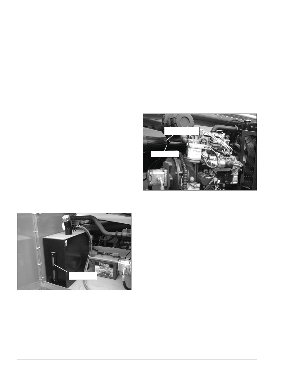
Air Filter
The air fi lter gauge (refer to Figure 7.4) has an indicator
to show when the fi lter needs replaced.
Figure 7.4 – Air Filter Gauge
To inspect the air fi lter:
3. At the lower controls, twist the emergency stop but-
ton clockwise and place the on/off switch to the on
position.
4. Press and hold the start button until the engine
starts.
5. Open the doors on the right side of the chassis
to access the air fi lter gauge (refer to Figure 7.4).
Check the clear zone after running the engine for 30
seconds.
If the indicator is red, replace the fi lter. After re-
placing the fi lter, press the reset button to reset
the indicator disk.
If the indicator is clear, the fi lter is OK.
6. Shut off the engine.
Electrical System
Electrical power is supplied from a 550 CCA, 12 V bat-
tery. The battery is behind the doors on the right side of
the chassis, next to the fuel tank (refer to Figure 7.5).
The battery supplies 12 V DC electrical power to oper-
ate the aerial platform electrical and electrohydraulic
components.
y
y
Air Filter Gauge
Reset Button
Air Filter Gauge
Reset Button