Snorkel S3246 CE User Manual
Page 24
Chapter 7 – Controls
20
S2646/3246 – 0410063EE
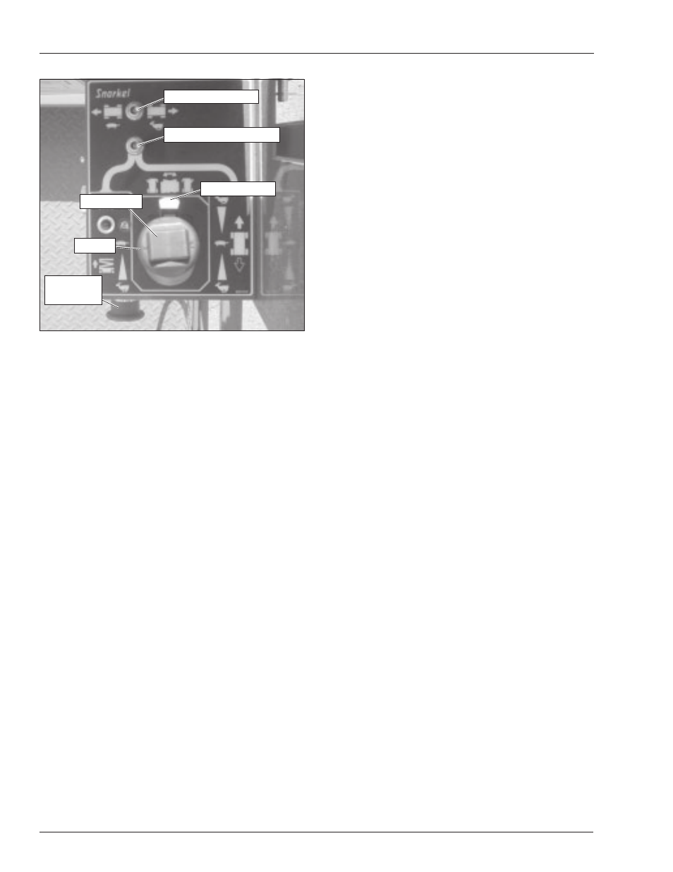
Figure 7.3 – Upper Controls
Emergency Stop Button
The emergency stop is a two-position red push button on
the front of the upper control box. Push the button in to
disconnect power to all control circuits at the upper con-
trols. Pull the button out to restore power.
Note
The lower controls override the upper controls. If the up-
per control emergency stop is engaged the lower con-
trols can still be used to operate the aerial platform.
Push the button in when the upper controls are not in use
to help protect against unintentional platform operation.
Drive/Lift Selector Switch
Place the drive/lift selector switch in the drive position to
drive the aerial platform using the joystick. The platform
will not raise or lower while driving.
Place the drive/lift selector switch in the lift position to
raise and lower the platform using the joystick.
Joystick
Use the joystick (refer to Figure 7.3) to operate the fol-
lowing functions.
• Aerial platform steering
• Aerial platform drive and speed
• Platform raise/lower and speed
Movement of the joystick in a given direction produces a
corresponding movement of the aerial platform. The steer-
ing and drive functions may be operated separately or
simultaneously.
Interlock
The joystick has an interlock switch in the handle. En-
gage the interlock by grasping the joystick and pulling
the switch toward the handle. Engage the interlock to
activate the steering, drive, or lift functions.
Steer Switch
The steer switch is a momentary contact, rocker switch
on top of the joystick. This switch controls the two front
wheels to steer the aerial platform.
To steer to the right, engage the interlock on the joystick
and hold down the right side of the steer switch. To steer
to the left, engage the interlock on the joystick and hold
down the left side of the steer switch.
Note
The steering wheels are not self-centering. Set the steer-
ing wheels straight ahead after completing a turn.
Drive Range Switch
The drive range switch has two positions to select drive
wheel operation:
• High (Rabbit) – for normal driving conditions.
• Low (Turtle) – for driving on grades up to 25 percent
that require low speed and high torque operation,
where high range is not sufficient to climb the grade.
Horn Button
The horn button is on the left side of the upper control
box. Press the button to sound the horn.
Battery Condition Indicator
The optional battery condition indicator gauge is on the
top of the upper control box. It indicates the level of avail-
able battery power to operate the aerial platform.
Steer Switch
Drive Range Switch
Interlock Switch
Drive/Lift Selector Switch
Emergency
Stop Button
Joystick