Snorkel MB20-sn1000+ User Manual
Page 25
2 - 15
2. Operation & Specifications
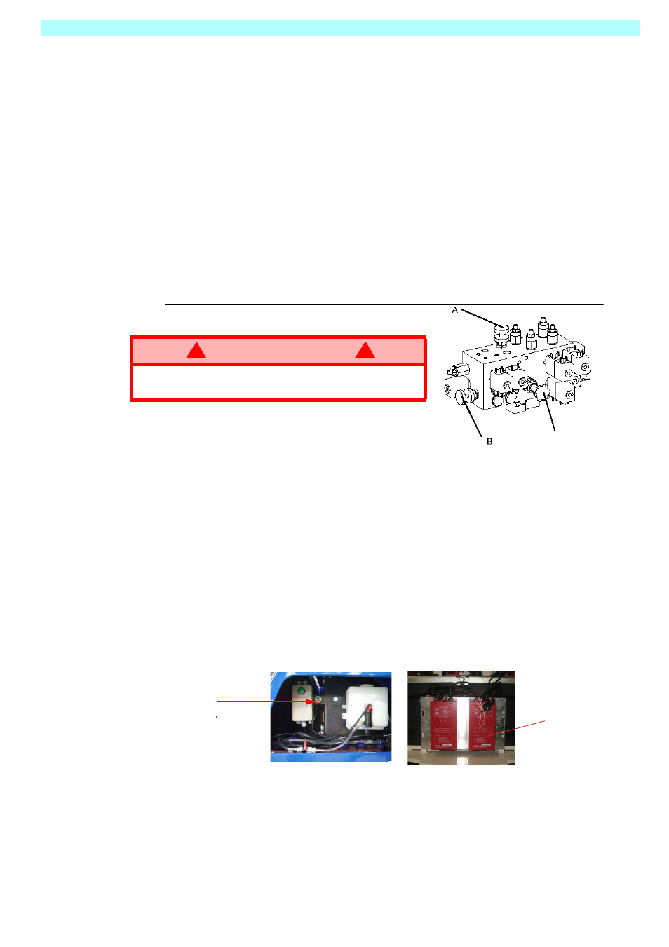
Proceed as follows:- (Refer to the valve block drawing Figure 6.)
1. Fully lower the jib boom and the mast sections. Rotate the mast into the stowed
position.
2. Turn the Upper Control Box Keyswitch to the OFF position and remove the key.
3. Remove the rear GRP cover from the chassis and locate the hydraulic control valve
block.
4. The hand valve marked ‘A’ should be turned fully clockwise to close. The hand valve
marked ‘B’ should be turned fully anti-clockwise to open.
5. Operate the red handpump a number of times to develop sufficient pressure to
‘separate’ the internal brake disks. These brakes are integral with the hydraulic drive
motors.
NOTE: The machine can now be safely towed or winched.
6. On completion of towing/winching, reverse the position of the rotary hand valves ‘A’
and ‘B’. The handpump becomes inoperative when the valves are returned to their
normal position.
2.6 A
FTER
U
SE
& S
TORAGE
A
FTER
U
SE
E
ACH
D
AY
1. Ensure that the platform (masts and jib) are fully lowered.
2. Park the machine on firm and level ground, never on a grass surface.
3. Turn the key switch to the OFF position and remove.
Handpump
4. Put the batteries on charge.
W A R N I N G
!
!
RISK OF SERIOUS INJURY. Releasing the brakes will cause the
machine to move uncontrollably on a slope. Damaging momentum
can be developed due to the large mass of a slow moving machine
Figure 6: Valve Block-Towing Valve
s
BATTERY CHARGING
Before charging check that:-
1.
The correct mains voltage and current is available to the charger.
The MB machine is fitted with a high output charging assembly. this consists of
two 24V 30A 900W Chargers. The chargers can be linked together if the supply
voltage and current are high enough to meet the power demand. If the power
supply is not good enough, a single charger can be used. If this option is taken,
it is important that charger ‘A’ is used, as it is the one linked to the remote display
for battery charge level.
2.
Check that the extension cord(s) is in good condition and is no longer than
8M (26fT). 1.5mm Sq (12 AWG) or larger cable is required. Ensure that the plug(s)
is of the correct rating and is compatible with the electrical installation into which
it will be plugged.
3.
The charger(s) will turn on automatically after going through a self test sequence.
the remote LED on the control Panel will indicate the status of charging.
‘A’
LED Remote
Charge indicator.