Class1 Digital Tank Level Display User Manual
Page 5
page 5 of 5 pages
Engineering
Standards
Name
Tank Level Display
Identifier
Installation Information
Engineering Standard Number
C1-102245-A
The tank level gauge has a bar traveling back and forth across the display.
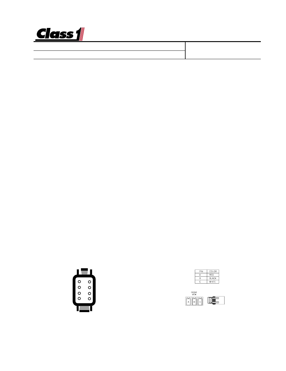
There is a problem with the pressure transducer (PN 102162) or wiring. At the
transducer connector, check for 5 VDC between pins A (+5 VDC) and pin B
(ground). These are sent from the display and must be of the correct polarity for
the transducer to function. Plug the connector into the transducer and check for
voltage between Pin B (sensor ground) and pin C (sensor signal) at the trans-
ducer. With an empty tank, this voltage should be between 500 mV and 900 mV, if
it is not, replace the transducer. Check for voltage at the display between pin 6
(sensor ground) and pin 2 (signal). With an empty tank, this voltage should be
between 500 mV and 900 mV. If it is not, check the wiring from the transducer to
the display. If the correct voltage is present at pin 2, replace the display.
The Tank Level Gauge does not change or calibrate.
There is a problem with the pressure transducer or wiring. At the transducer
connector, check for 5 VDC between pins A (+5 VDC) and pin B (ground). These
are sent from the display and must be of the correct polarity for the transducer to
function. Plug the connector into the transducer and check for voltage at the
display between pin 6 (sensor ground) and pin 2 (signal). With an empty tank, this
voltage should be between 500 mV and 900 mV. As the water level in the tank
increases, the voltage should increase. If it does not, then replace the transducer
If the voltage increases, and the display does not change, attempt to calibrate the
unit. If calibration does not correct the problem, replace the display.
1
2
3
4
8
7
6
5
Wire Insertion View