Pressurized tanks – Class1 Digital Tank Level Display User Manual
Page 2
page 2 of 5 pages
Engineering
Standards
Name
Tank Level Display
Identifier
Installation Information
Engineering Standard Number
C1-102245-A
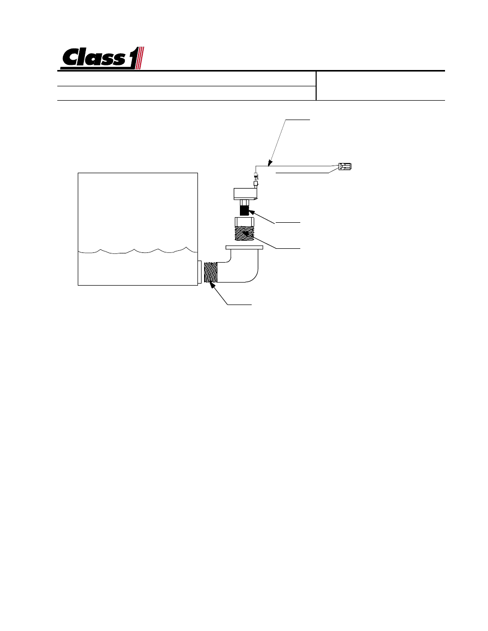
Harness
102193 5'
102194 10'
102195 20'
Pressure Transducer
1/4 NPT
Adapter 3/4-1/4 NPT Bushing (OEM)
Foam adapter is supplied when a
foam level system is ordered.
3/4 NPT Elbow (OEM)
FLUID TANK
Tank Level Gauge
Transducer Installation
The transducer must be mounted vertically as depicted to insure an accurate and reliable reading.
This will also prevent damage to the transducer from freezing.
The transducer measures the column of water in the tank above the opening of the elbow.
When calibrating for a full tank it is important that the tank not be overfilled. If the fill opening or
tank vent is above the transducer, care should be taken not to have water in this area when
calibrating the tank level gauge. The transducer should never be mounted in the sump area
because of sludge and potential inaccuracies in calibration.
Mount a 3/4 NPT elbow just off the bottom of the tank, enough to keep sediment out of the
elbow and transducer (PN 102162). Attach a 3/4 to 1/4 NPT adapter (supplied for foam) to the
elbow and mount the transducer to that. The elbow and adapter need to be installed so that
the transducer is mounted vertically.
Pressurized Tanks
If you have a pressurized tank, two pressure transducers (PN 102471) can be used to com-
pensate for pressure or vacuum in the tank. One transducer should be mounted near the
bottom of the tank and one near the top.
Use “Y” harness (PN 102439) and two (2) (PN 102455) transducer harnesses for wiring this
application.
When calibrating the dual transducer installation, the tank should be vented to the atmosphere.