Wire view of aem ems – AEM 30-6620 Series 2 Plug & Play EMS User Manual
Page 9
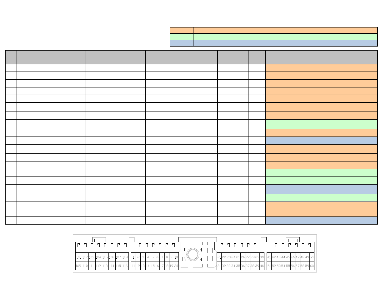
Connection Diagram for EMS P/N 30-6620
Pin
‘89-‘98 Nissan Skyline RB26DETT,
‘93-‘98 Nissan Skyline RB25DET,
‘89-‘94 Nissan Skyline RB20DET
1990-1995 Nissan 300ZX
VG30DE, VG30DETT, 1992-
1994 Nissan Maxima VE30DE
‘94-‘96 Nissan Silvia S14 SR20DET,
‘88-‘91 Nissan Silvia S13 CA18DET,
‘89-‘93 Nissan 180SX CA18DET
AEM EMS
30-6620
I/O
Notes
1
Ignition 1
Ignition 1
Ignition 1
Coil 1
Output
PnP for Coil 1, 0-5V rising edge trigger
2
Ignition 5
Ignition 2
Ignition 2
Coil 5
Output
PnP for Coil 5, 0-5V rising edge trigger
3
Ignition 3
Ignition 3
Ignition 3 (CA18DET only)
Coil 3
Output
PnP for Coil 3, 0-5V rising edge trigger
4
AAC Valve
←
---
PW 1
Output
PnP for Idle Air Control, connects to Pin 106
5
A/T Control Unit
←
Wastegate Solenoid (JDM CA18 only)
PW 2
Output
PnP for Boost control, connects to Pin 25
6
Cooling Fan Relay
(RB26DETT only)
Cooling Fan Sub Relay
(300ZX Turbo Only)
Air Conditioner Relay (CA18DET only)
Low Side 5
Output
PnP for Cooling Fan (CA18DET only: PnP for AC)
7
Tachometer
←
←
Low Side 7
Output
PnP for Tachometer, internal pull-up resistor to 12V
8
---
AIV Solenoid (90-92 300ZX),
Power Solenoid (Maxima)
Variable Butterfly Solenoid
(JDM CA18DET only)
Low Side 12
Output
Available, switched Ground, 1.5A max
9
Air Conditioner Relay
←
←
Low Side 6
Output
PnP for A/C Compressor
10
ECM Ground
←
←
Power Ground
Input
Dedicated
11
Ignition 6
Ignition 4
Ignition 3 (SR20DET only)
Ignition 4 (CA18DET only)
Coil 6
Output
PnP for Coil 6, 0-5V rising edge trigger
12
Ignition 2
Ignition 5
Ignition 4 (SR20DET only)
Coil 2
Output
PnP for Coil 2, 0-5V rising edge trigger
13
Ignition 4
Ignition 6
---
Coil 4
Output
PnP for Coil 4, 0-5V rising edge trigger
14
A/T Control Unit
←
←
Idle 5
Output
Avail, switched Ground / +12V, 1.5A Max
15
A/T Control Unit
←
←
Idle 6
Output
Avail, switched +12V / Ground, 1.5A Max
16
ECCS Relay control,
Ignition Relay control
←
←
Main Relay
(control)
Output
Dedicated, EMS activates relay with switched GND
17
---
Data Link Connector
Data Link Connector
Injector 7
Output
Avail, Switched Ground, 1.5A max
18
Fuel Pump Relay Control Signal
←
←
Low Side 1
Output
PnP for Fuel Pump
19
Power Steering Oil Pressure Switch
Cooling Fan Relay
Cooling Fan Relay (SR20DET only)
Low Side 3
Output
PnP for Cooling Fan
20
ECM Ground
←
←
Power Ground
Input
Dedicated
Wire View of AEM EMS
PnP
These pins are used in the AEM-supplied startup calibration. They can be reconfigured by the end user.
Available
Not used by the startup calibration. Modifications to the OEM wiring may be required before use.
Dedicated
The location of these pins is fixed and must not be changed.