AEM 30-6052 Series 2 Plug & Play EMS User Manual
Page 8
Page 8 of 11
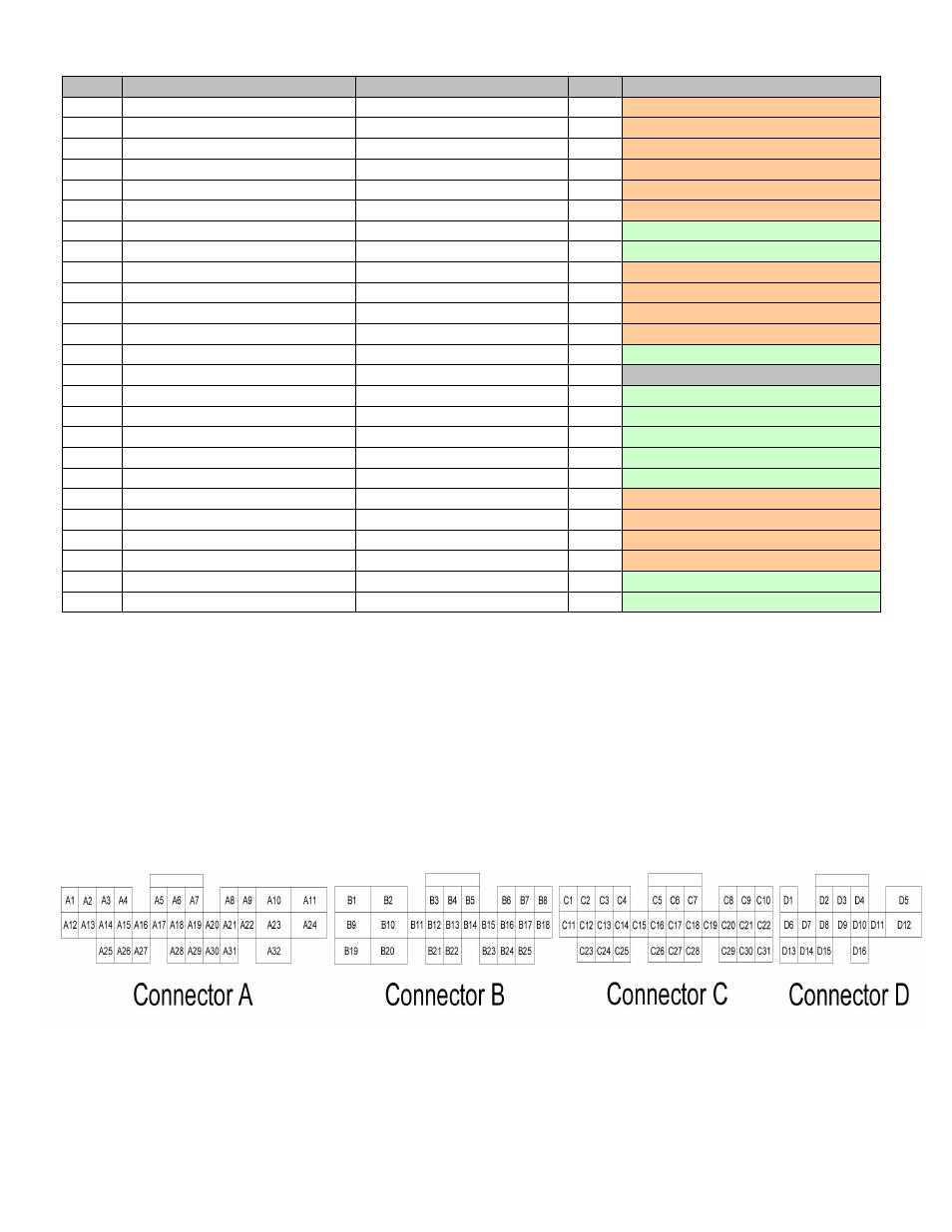
Pin #
2000-2005 S2000
AEM EMS 30-6052
I/O
Availability
B1
Power Source 1
+12V Switched
Both
Dedicated
B2
Power Ground 1
Power Ground
Both
Dedicated
B3
Injector 2
Injector 2
Output
PnP For Injector 2
B4
Injector 3
Injector 3
Output
PnP For Injector 3
B5
Injector 4
Injector 4
Output
PnP For Injector 4
B6
---
PW 1i
Output
PnP For Idle Control Solenoid
B7
---
High Side Driver 2
Output
Avail, Switched +12v, 1.5A Max
B8
---
Idle #5
Output Avail, Switched Ground, 1.5A Max
B9
Power Source 2
+12V Switched
Both
Dedicated
B10
Power Ground 2
Power Ground
Both
Dedicated
B11
Injector 1
Injector 1
Output
PnP For Injector 1
B12
VTEC solenoid Valve
High Side Driver 1
Output
PnP For VTEC Solenoid
B13
---
Coil 1
Output
**This pin connects to C4 also**
B14
---
---
---
Not Used
B15
---
PW1
Output **This pin connects to B23 also**
B16
---
Injector 8
Output Avail, Switched Ground, 1.5A Max
B17
---
Idle #6
Output
Avail, Switched +12v, 1.5A Max
B18
---
Idle #7
Output Avail, Switched Ground, 1.5A Max
B19
---
Injector 6
Output Avail, Switched Ground, 1.5A Max
B20
Logic Ground 1
Power Ground
Both
Dedicated
B21
Voltage Back Up
Permanent +12V
Input
PnP For Perm Power
B22
Logic Ground 2
Power Ground
Both
Dedicated
B23
Idle Air Control Valve
PW1
Output
PnP For Idle Control Solenoid
B24
---
Knock 2
Input
Available, software knock filter
B25
---
Idle #8
Output
Avail, Switched +12v, 1.5A Max