AEM 30-3502 Infinity Plug & Play Harnesses - Honda/Acura K-Series Engine User Manual
Page 9
2001–2005 Honda K Series
9
© 2014 AEM Performance Electronics
Infinity
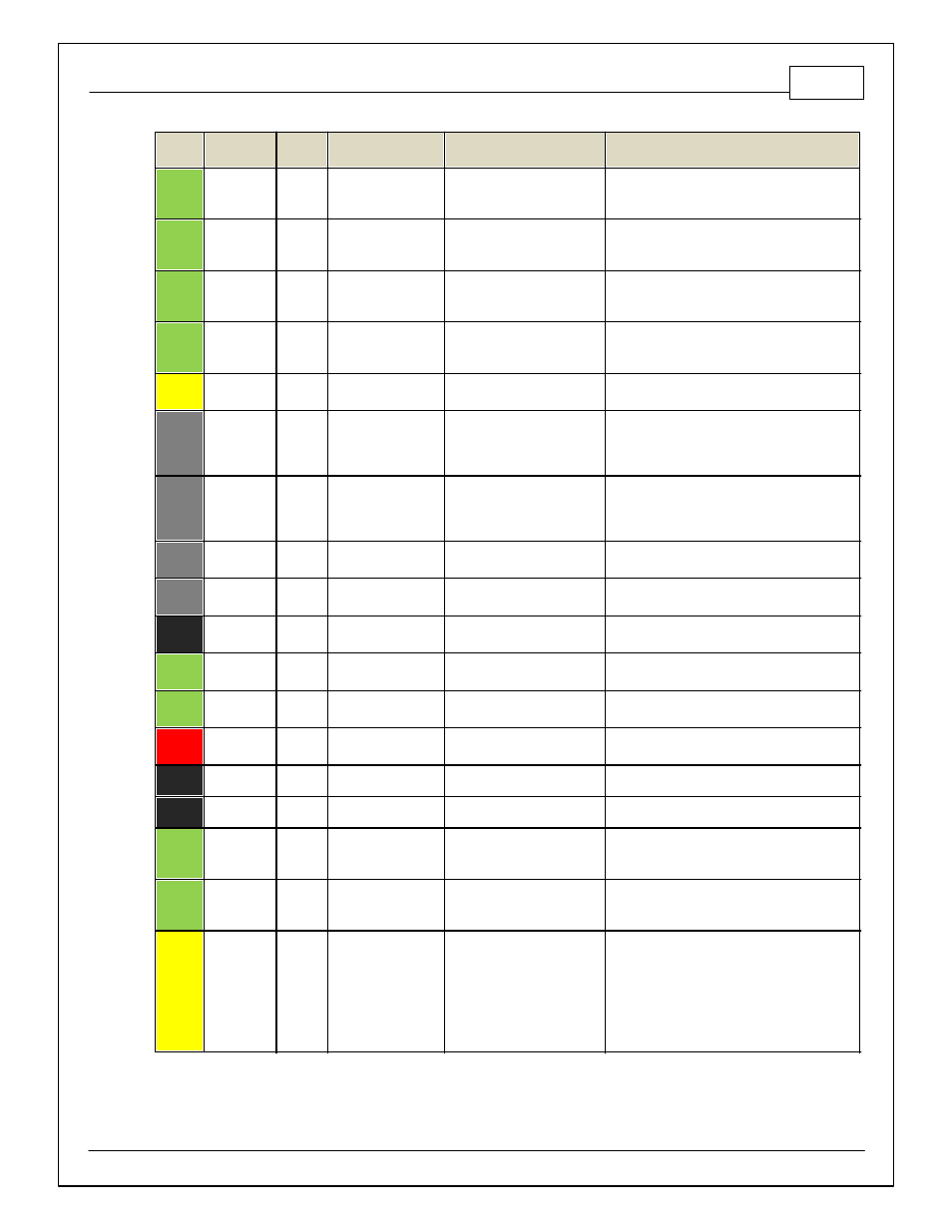
Pin
Infinity
Assignment
Honda
Pin
Honda Description
Infinity Hardware
Specification
Notes
54
VR2 (+) -
Driv en
Wheel
---
---
Dif f erential Variable
Reluctance Zero Cross
Detection
See Driv en Wheel Speed Calibration in the Setup
Wizard Vehicle Speed page.
55
VR2 (-) -
Driv en
Wheel
---
---
Dif f erential Variable
Reluctance Zero Cross
Detection
See Driv en Wheel Speed Calibration in the Setup
Wizard Vehicle Speed page.
56
VR3 (-) -
Tag Wheel
---
---
Dif f erential Variable
Reluctance Zero Cross
Detection
See Non Driv en Wheel Speed Calibration in the
Setup Wizard Vehicle Speed page.
57
VR3 (+) -
Tag Wheel
---
---
Dif f erential Variable
Reluctance Zero Cross
Detection
See Non Driv en Wheel Speed Calibration in the
Setup Wizard Vehicle Speed page.
58
HS Out 0
B15
VTEC solenoid Valv e
0.7A max, High Side Solid
State Relay
+12V High Side Driv e. See Setup Wizard Honda
VTEC page f or options.
59
Stepper_1B
---
---
Automotiv e, Programmable
Stepper Driv er, up to 28V and
±1.4A
Be sure that each internal coil of the stepper
motor is properly paired with the 1A/1B and 2A/2B
ECU outputs. Supports Bi-Polar stepper motors
only .
60
Stepper_2B
---
---
Automotiv e, Programmable
Stepper Driv er, up to 28V and
±1.4A
Be sure that each internal coil of the stepper
motor is properly paired with the 1A/1B and 2A/2B
ECU outputs. Supports Bi-Polar stepper motors
only .
61
HBridge0_0
---
---
5.0A max Throttle Control
Hbridge Driv e
62
HBridge0_1
---
---
5.0A max Throttle Control
Hbridge Driv e
63
+12V
A2/B1
Main Power
Main Power
12 v olt power f rom relay powers the Inf inity ,
Lambda sensor, and AEMNet
64
Injector 6
---
---
Saturated or peak and hold, 3A
max continuous
Spare injector output Injector 6
*No peak and hold injector f or Inf inity 8h
65
Injector 5
---
---
Saturated or peak and hold, 3A
max continuous
Spare injector output Injector 5
*No peak and hold injector f or Inf inity 8h
66
Injector 4
B2
Injector 4
Saturated or peak and hold, 3A
max continuous
Injector 4
*No peak and hold injector f or Inf inity 8h
67
GND
---
---
Power Ground
Connects directly to ground
68
+12V
A3
Main Power
Main Power
12 v olt power f rom relay powers the Inf inity
69
Ana19 -
APP2
---
---
12 bit A/D, 100K pullup to 5V
0–5V analog signal. Do not connect signals
ref erenced to +12V as this can permanently
damage the ECU.
70
Ana18 -
APP1
---
---
12 bit A/D, 100K pullup to 5V
0–5V analog signal. Do not connect signals
ref erenced to +12V as this can permanently
damage the ECU.
71
Ana16
- Mode SW
---
---
12 bit A/D, 100K pullup to 5V
0–5V analog signal. Use +5V Out pins as power
supply and Sensor Ground pins as the low
ref erence. Do not connect signals ref erenced to
+12V as this can permanently damage the ECU.
See the 1D lookup table 'Mode Switch' f or input
state.
Also assignable to multiple f unctions. See Setup
Wizard f or details.