Pin installation – AEM 30-3323 Wiring Harness for V2 Controller with Internal MAP Sensor User Manual
Page 3
Page 3
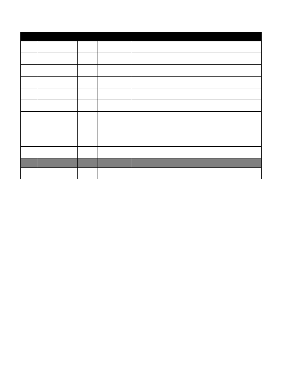
Pin Installation
Pin #
Description
Wire**
Color
Connection
1
Pump Ground
16
AWG
Orange
Connect to ground (black) wire of pump.
2
LED -
20
AWG
Gray
Connect to ground (black) wire of external LED.
3
LED +
20
AWG
Violet
Connect to positive (red) wire of external LED.
4
Solenoid -
20
AWG
Brown/White
1.5A Low Side output. Connect to optional flow control solenoid.
5
Boost Safe LS Out
18
AWG
Green
1.7A Low Side output. Grounded when error condition exists.
6
Pump Power
16
AWG
Pink
Connect to the positive (red) wire of pump.
7
Ground
16
AWG
Black
Main ground connection, connect directly to battery ground.
8
Level Switch+
20
AWG
White
Connect to the white wire of the fluid tank level sensor*
9
Level Switch-
20
AWG
Brown
Connect to the black wire of the fluid tank level sensor*
10
Arm Switch +
20
AWG
Yellow
Arms injection system. Connect to a switched 12V source.
11
Empty-Not Used
Not Used
12
Power 12V
16
AWG
Red
Main Power Connection, connect directly to positive battery
terminal.
*Note: If fluid tank is equipped with previous generation level sensor, identified by having two black wires, then
pins 8 (white) and 9 (brown) may be connected to either of the two black sensor wires. The polarity is
unimportant.
**Note: If you need to extend the wires to mount the controller use at least 16 AWG wire for the pump and
controller ground circuits and 18 AWG for the remainder.