AEM 30-2067 X-WiFi Wideband UEGO & EGT Controller User Manual
Page 7
Page 7
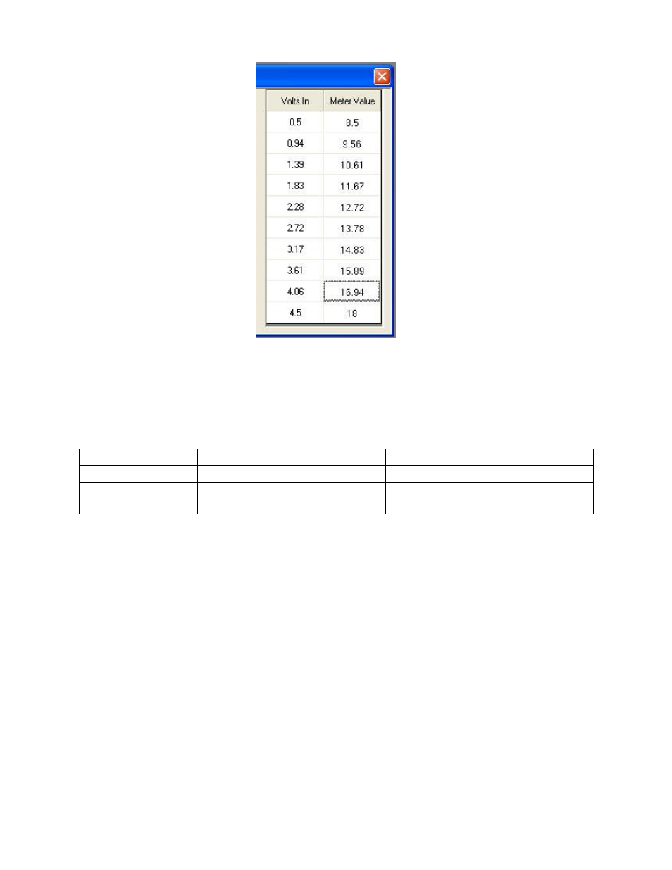
Connect the WHITE Analog Output + wire to the Aux Gauge input and the BROWN
Analog Output
– wire to the sensor ground. Table 4 below lists the Lambda and Sensor
ground pin locations for the different FIC part numbers.
AEM F/IC P/N
Lambda Pin
Sensor GND Pin
30-1910(X)
Pin 18 of 22-pin connector
Pin 5 of 22-pin connector
30-1930(X)
Pin 18 of 22-pin connector
Pin 20 of 20-pin connector
Pin 5 of 22-pin connector
Thermocouple Mounting
The optional thermocouple comes with a stainless steel compression style mounting
adapter. The mounting adapter consists of three pieces: compression nut, ferrule
sleeve, threaded body. The threaded body has 1/8” NPT male threads. To install the
sensor, the threaded body can either be threaded into a hole with mat
ing 1/8” NPT
threads, or welded to the pipe/manifold. Remove the compression nut, ferrule sleeve,
and thermocouple from the threaded body. For a welded installation, drill a 13/32” hole
and weld the threaded body, being careful not to cause any distortion. . For a threaded
installation, either thread the body into an existing hole with 1/8” NPT threads or drill a
hole using an “R” size drill bit and cut the threads using a 1/8” NPT tap. With the
compression nut and ferrule sleeve on the thermocouple, insert the thermocouple into
the threaded body so the tip of the thermocouple is near the center of the pipe/manifold
and tighten the compression nut to the threaded body. See Figure 6. Table 5 below
lists some of the common EGT measurements and corresponding thermocouple
mounting locations.
Figure 5. F/IC Aux Gauge Setup
Table 4. F/IC Pin Locations