J.P. Instruments EDM 900 Pilots Guide User Manual
Page 17
For Your Safe Flight
Page 17
Section 3 - Displays and Controls
The EDM monitors engine temperatures, pressures and voltages, assists
in adjusting the fuel/air mixture, and helps diagnose engine malfunctions.
There are multiple components of the user interface:
Four front panel operating buttons below the bottom of the display.
RPM and MAP display in the upper left corner of the display
Scanner analog display including cylinder number and index square
in the lower left corner of the display
Scanner digital display for numeric readouts and messages at the
bottom left
Bar graph displays on the right half of the display
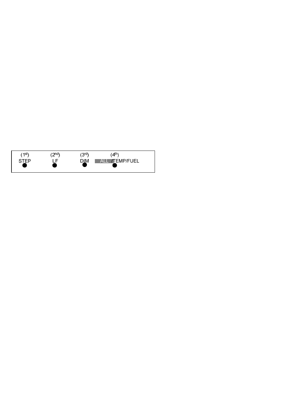
Control Buttons
Four operating buttons control all functions of the EDM. These buttons
may change labels depending on the current operating mode of the EDM.
The term tap is used to denote pressing a button momentarily. The term
hold is used to denote pressing and holding a button for five seconds or
longer. Button layout is shown below:
1st Button
In the Automatic mode, tapping the STEP button stops Scanner auto-
sequencing and changes to Manual mode. Each tap of the STEP
button then displays the next measurement in the sequence. Holding
the STEP button sequences in reverse order.
In the LeanFind mode tapping the EXIT button will terminate the
LeanFind mode and change to the Automatic mode.
In the Program mode tapping the NEXT button will advance to the
next item.
2
nd
Button
In Automatic or Manual modes, tapping the LF button will activate the
LeanFind mode.