Attaching the square tubing to the frame of the ap, Press, Inserting the cam wire into the assembly – Hornady Lock-N-Load Case Feeder User Manual
Page 6: Adding the case slide on to the sub-plate
¼-20 1 ¼" Cap Screw (Full Size)
5
4
5
4
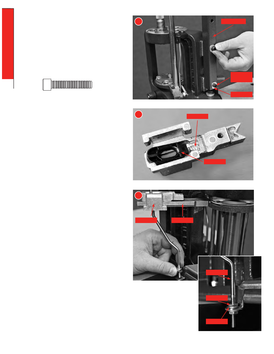
Attaching the Square Tubing to the
frame of the AP
™
Press.
Place the ¼" Flat Washers (48) on the ¼-20 x 1 ¼" Socket
Head Cap Screw (SHCS) (47).
Place one SHCS through the Square Tubing (49) and thread
into the Frame.
Repeat for the second Screw.
Tighten both screws down using a 3/16" Allen wrench.
3
3
Head Cap
Screw
Flat Washer
Square Tubing
Inserting the Cam Wire into the
Assembly.
Raise the Ram to the top of the stroke.
Screw one #10-32 Hex Nut (41) onto the Cam Wire (43)
approximately 1" from the end.
Place one of the #10 Flat Washers (67) onto the Cam Wire.
From the bottom of the Sub-Plate, slide the non-threaded
end of the Cam Wire through the slot of the Sub-Plate and
through the Case Slide (38).
Place the threaded end of the Cam Wire through the hole of
the tab on the Main Bracket.
Place the other Flat Washer and Hex Nut onto the bottom of
the Cam Wire and tighten finger tight.
Lower the Ram.
Guide
Case Slide
Sub-Plate
Cam Wire
Hex Nut
Flat Washer
Spring
Adding the Case Slide on to the
Sub-Plate
Assemble the Case Slide by placing the Spring (40) in the
relief of the Slide and hooking the relief of the Guide (39) onto
the end of the Spring. Slide the Guide forward and compress
the Spring until the Guide fits into the pocket. You may need
to hold the Guide and Spring into the Slide with your finger as
you slide the assembly back onto the “Sub-Plate.”
- 6 -
ASSEMBL
Y
ASSEMBLY: CASE FEEDER