Ford f-150 tool box step installation instructions – CARR 172004 Tool Box Step User Manual
Page 2
Ford F-150 Tool Box Step Installation Instructions
Part No’s: 172001, 172002 & 172004
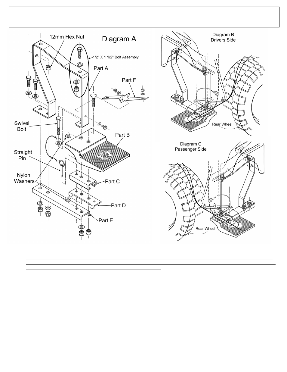
1. Take Parts A-F and assemble them together as shown on Diagram A with the straight pin installed. IMPORTANT NOTE: Part D is a
critical safety component. Notice the tabs on the part. Which ever side you are placing the Tool Box Step on your vehicle, the tabs on
Part D must be facing down and towards the rear wheel when it is in the straight position. Diagram A exploded assembly shows Part
D in the passenger side position. Diagram B shows Part D in the driver’s side position. Diagram C shows Part D in the passenger side
position. Part D keeps your step from swiveling back into the rear wheel.
2. Do not install the final 12mm hex nut and ½” x 1 ½” bolt assembly. Do not tighten the bolts all the way; leave the assembly loose to
make it easier to attach to your vehicle.
3. Take the entire assembly and position it up against the body metal underneath as shown in Diagrams B & C. IMPORTANT: Make
sure you get the Driver and Passenger assembly on the correct side. The back hole in Part A fits over a 12mm treaded bolt. The front
hole in Part A lines up with a hole in the body metal where you will take the ½” x 1 ½” bolt assembly and fasten it to the vehicle.
4. While holding the entire assembly in position, take the 12mm hex nut (this is not a nylon lock nut) (we do recommend putting a small
amount of red Lock Tite on the bolt before placing the 12mm hex nut on) and hand tighten the back of Part A to the extended 12mm
bolt and take the ½” x 1 ½” assembly and hand tighten the front of Part A to your vehicle.
5. Take Part F and install it as shown in Diagrams B & C with the 6mm bolt, washer and nut provided.
6. With all the mounting hardware loose, line up the entire step assembly so that the step is level and straight in relationship to your
truck’s body metal.
7. Tighten all mounting hardware while keeping step level.
8. Go ahead and tighten all other hardware. NOTE: We recommend when tightening the ½” x 3” swivel bolt assembly, do not over
tighten it so that you can swivel the step out of the way when not in use. It should not move easily. There should be some drag when
you move the parts.
9. You can swivel the step out of the way by pulling the straight pin.
10. When you do swivel the step out of the way, be sure to install the straight pin in the back hole of Part C & D assembly.
11. Repeat the above instructions for the other side.
12. Your Tool Box Step is ready for use.