CARR 102564 Hoop II Multi-Mount Step User Manual
Page 3
HOOP II MULTI-MOUNT STEP INSTALLATION INSTRUCTIONS
Part No.’s: 102561, 102562 & 102564
WARNING: Do not over tighten nuts and bolts, or damage to the casting and or stripping of the threads could result.
WARNING: FOR SAFE AND PROPER USAGE OF THIS PRODUCT, THE MOUNTING INSTRUCTIONS MUST BE FOLLOWED CAREFULLY AND COMPLETELY.
IMPORTANT: The manufacturer and distributor of this product are in no way responsible for the consumer's failure to adhere to the warnings and directions of these instructions,
in the event of damage to the consumer's vehicle, other properties and or personal injury.
ITS PAINTABLE
All of the bright finished products can be painted to whatever color you like. Simply sand your bright finished step lightly
all over, prime it with “Synthetic Zinc Chromate Primer”, let dry, and it’s ready to paint.
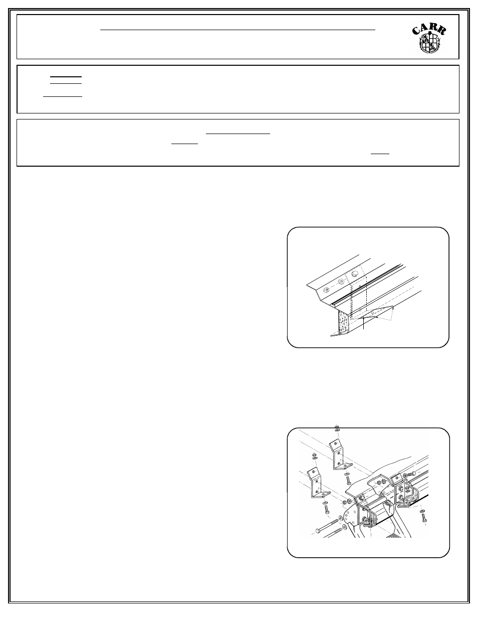
PENCIL LINES ON
PINCH WELD
PENCIL LINE ON UNDERSIDE OF
STEEL BRACKET BOTTOM FLANGE
Diagram 4
Diagram 5
*8. Take an unused steel bracket and place in the same spot as where the drilled hole and lines are.
(Also note Step 24)
9. Put one of the 5/16“ bolts through the body metal from the
open door side and through the steel bracket. Line up the
bracket with the marked lines. Mark two more lines on the
outside of the pinch weld that line up with the lines inside of the
pinch weld. Also, using the edge of the pinch weld as a guide,
mark another line across the bottom of the foot of the steel
bracket (refer to diagram 4).
10. Take the 5/16 bolt out and remove the steel bracket. Measure
the distance from the marked line across the foot of the steel
bracket and the center of the hole.
11. Take the dimension from step 10 and measure the same
distance from the pinch weld. Mark a line on the body metal
centered between the other outside lines.
12. Measure across the outside lines and mark another line that will
cross the line you marked in Step 11.
13. Center punch where the lines cross.
14. Stuff a rag between the body metal and the A/C and rear heater lines to push the lines up out of the way while
drilling.
15. Before drilling, take the steel bracket and slip it between the body metal and the A/C and rear heater lines for
protection when drilling.
16. With a sharp 1/8" drill bit, drill out the center punched area. Go
back and drill out the 1/8" hole with a 5/16" drill bit.
17. Place the steel bracket back into place. Put a 5/16" bolt in both
holes to see if the holes in the body metal line up with the holes
in the steel bracket. If the holes do not line up, take a round file
or a power grinder and enlarge the hole until the bolts fit.
18. Repeat the steps for drilling out the holes for the other steel
bracket.
19. With all the holes drilled, place your step back into position.
Use the 5/16" hardware provided and hand tighten the front
steel bracket to the vehicle. (Refer to Diagram 5).
20. Take additional hardware and hand tighten the rear steel bracket
to the vehicle. NOTE: if the rear bracket holes do not line up,
loosen the bolts on mounting foot. This should give enough play to get the holes to line up.
21. With everything in its proper place, go back and securely tighten all the hardware.