Installing dust filter, Zone control panel function and installation, Fig. 6 – L.B. White I-34 Infraconic Spark Ignition User Manual
Page 11: Optional), Important
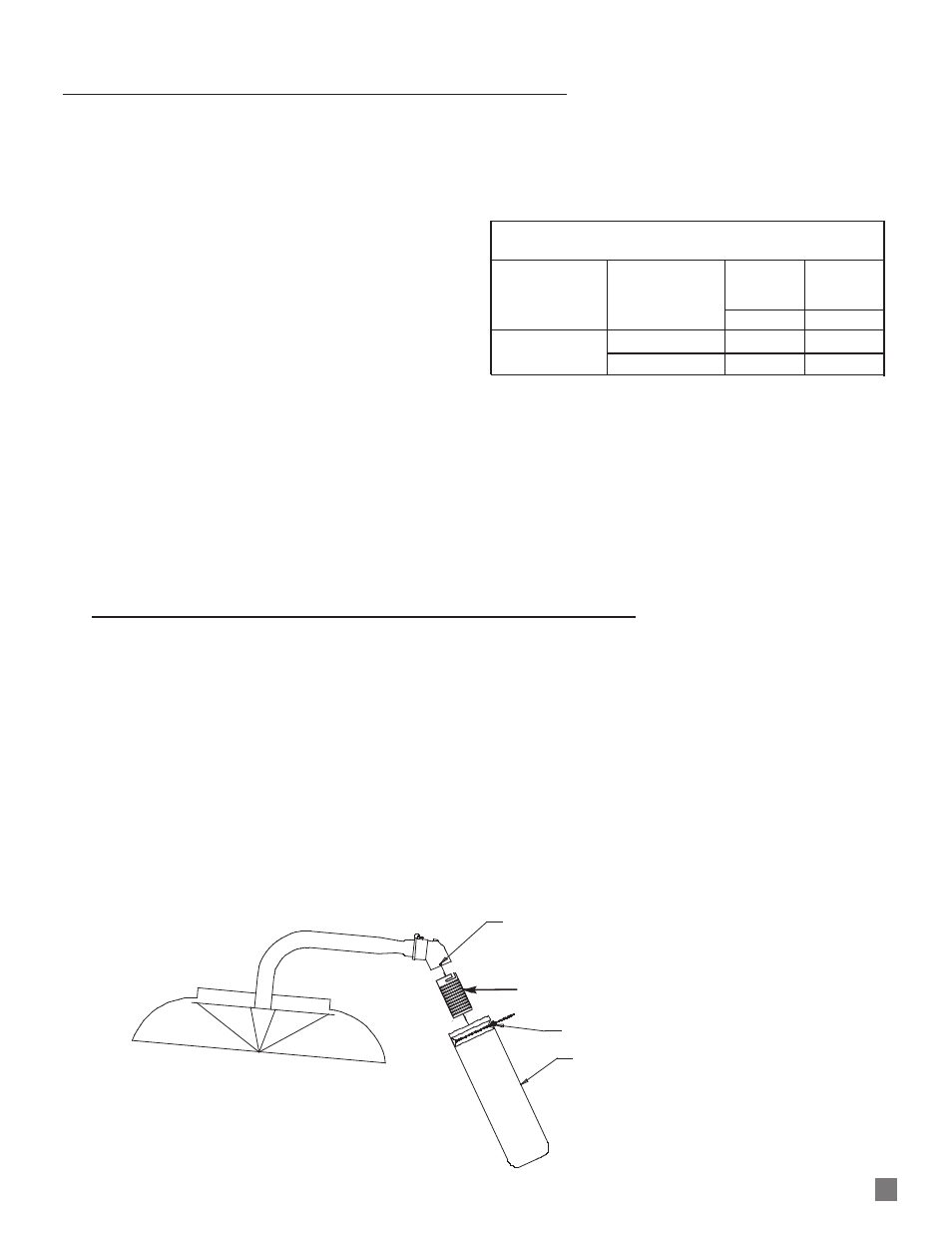
INJECTOR BODY TABS
FILTER ADAPTER
PART #23931
BEADED CABLE TIE
DUST FILTER
PART #23953
1100
INSTALLING DUST FILTER
FIG. 6
With proper (5 PSIG) gas pressure supplied, spark ignition
heaters will operate in the standard ON/OFF mode when
electrically connected to a building environment controller or
thermostat
If you require two stages of heat for greater temperature
control, a two stage solenoid operated zone panel must be
installed. This panel incorporates solenoids to control the
first and second stage heating levels as well as a pressure
regulator to set the firing rate of the first stage. Use of this
panel requires a two stage thermostat or a building
controller capable of controlling the heat in two stages.
When energized by a building controller or thermostat, the
zone panel’s first stage solenoid opens providing 2 PSIG,
controlled by the regulator on the zone control panel, to the
heater. This represents approximately half the heater’s full
output. If this level of heating does not satisfy the demand,
the building controller or thermostat will call for the second
stage of heating, full output, by energizing the second stage
solenoid. This provides 5 PSIG to the heater.
As the heat demand is satisfied, the building controller or
thermostat will reduce the firing rate by closing the second
stage solenoid and lastly the first stage solenoid if heat is no
longer needed.
Two stage zone panels are available in high or medium
capacity configurations and will control the following quantity
of heaters depending on fuel type.
All zone control panels must have an adjustable high
pressure regulator installed upstream of the inlet of the
panel. This regulator may be purchased from PSI as an
optional accessory. The regulator must be capable of
handling a maximum inlet pressure of 10 psi, while
supplying an outlet pressure of 5 psi nominal.
Separate installation instructions accompany each zone
panel.
ZONE CONTROL PANEL
FUNCTION AND INSTALLATION
(Optional)
Solenoid Zone Control System
Medium
High
Model and
Capacity
Capacity
Heat Output
Fuel
Panel
Panel
Quantity
Quantity
I34
L. P. Gas
7
20
(34,200 BTUH)
Natural Gas
4
20
INJECTOR
BODY
TABS
FILTER SLEEVE
PART #20421
BEADED
CABLE TIE
DUST FILTER
PART #81649
FILTER SLEEVE
IMPORTANT
This filter kit is designed to provide additional dust filtration
capability and capacity for Infraconic heaters when installed
in severely dusty environments.
1. Attach filter sleeve to injector body. The injector body
tabs fit into the slots on the sleeve. Rotate the sleeve
to lock it onto the injector body.
2. Position the filter onto the sleeve. Ensure all sleeve
holes are covered by the filter.
3. Securely attach the filter to the sleeve using the
beaded cable tie.
4. Ensure filter does not sag or touch heater’s canopy.
FILTER