Split-shaft pto gearbox, Figure 2. rga gearbox component identification – Hale RGA User Manual
Page 6
SPLIT-SHAFT PTO GEARBOX
INSTALLATION MANUAL
4
CAUTION: When driving high inertia
auxiliary equipment such as a generator,
make sure the equipment shaft stops
rotating before shifting back to ROAD
position. Shifting to road position before
the shaft stops turning will result in
damage to gears.
The gearbox is shifted back to road position
by placing the apparatus transmission in
neutral and waiting until auxiliary
component shaft has stopped turning.
Movement of the shift controls while the
apparatus transmission is in neutral will
engage the drive shaft to drive the
apparatus.
NOTE: In most cases cooling water must
be connected to the gearbox when the
power required for the auxiliary
component is 200 hp (149 kw) or greater.
Gearbox coolers permit operation in a wide
range of ambient temperatures. An
integral gearbox cooler is standard on the
RGA gearbox and an optional auxiliary
cooler can be ordered to attach to the
MGA gearbox. For operation in temperate
climates the gearbox cooler must be
connected when the power required for
the auxiliary component is 200 hp (149 kw)
or greater. When apparatus is operated in
environments where high ambient
temperatures are normally encountered,
such as tropical regions, the gearbox cooler
must be connected when the power
requirement for auxilary components is less
than 200 hp (149 kw). Conversely when the
apparatus is normally operated in
environments where low ambient
temperatures are encountered the
gearbox cooler may not be required unless
the auxiliary equipment power requirement
is well above 200 hp (149 kw). ALWAYS
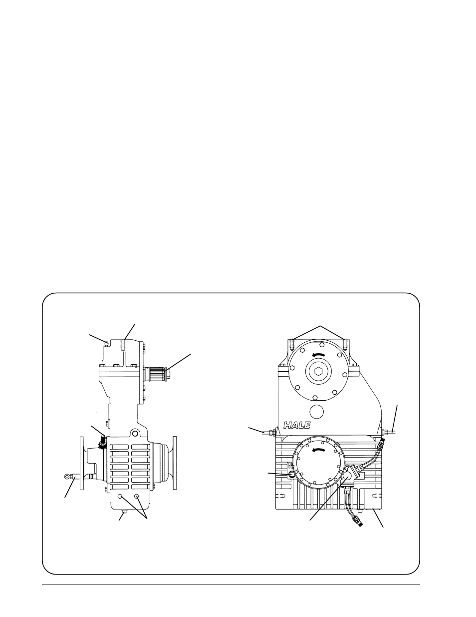
Figure 2. RGA Gearbox Component Identification
FRONT
DRIVE
FLANGE
REAR
DRIVE
FLANGE
AUXILIARY DRIVE
SHAFT
(2 INCH x 10 SPLINE)
SUPPORT BRACKET
MOUNTING HOLES
(5/8-11 UNC x 1 INCH DEEP)
AIR VENT
SHIFTING
SHAFT
OIL DRAIN
PLUG
GEARBOX MOUNTING HOLES
(5/8-11 UNC x 1 INCH DEEP)
OPTIONAL
SPEED
COUNTER
COOLING
WATER
CONNECTION
OIL FILL
AND LEVEL
PLUG
SERIAL
NUMBER
PLATE
LOOKING TOWARDS FRONT OF APPARATUS
GEARSHIFT SHAFT CAP AND
SHIFT INTERLOCK SWITCHES
SUPPORT BRACKET
MOUNTING HOLES
(5/8-11 UNC x 1 INCH DEEP)
COOLING
WATER
CONNECTION
REAR
DRIVE
FLANGE
TO FRONT OF APPARATUS