Bryant Hat Pump 698B User Manual
Page 5
C.
REFRIGERANT TUBING AND FILTER DRIER
CAUTION:
Installation of filter drier in liquid line is
required.
Connect vapor tubing to fittings on outdoor unit vapor service
valve. Connect liquid tubing to filter drier. (See Table 1 and Fig.
9.) Use refrigerant grade tubing. Connect other end of filter drier
to adapter tube on liquid service valve.
D.
SWEAT CONNECTION
CAUTION:
To avoid valve damage while brazing, ser-
vice valves must be wrapped in a heat-sinking material
such as a wet cloth.
Wrap service valves and filter drier with a wet cloth or heat-
sinking material. Braze connections using either silver bearing or
non-silver bearing brazing material. Do not use soft solder
(materials which melt below 800°F). Consult local code require-
ments.
CAUTION:
To prevent damage to unit or service valves,
observe the following:
• Use a brazing shield.
• Wrap service valves with wet cloth or use a heat sink
material.
E.
LEAK CHECKING
Leak test all joints in indoor, outdoor, and refrigerant tubing.
F.
EVACUATE REFRIGERANT TUBING AND
INDOOR COIL
CAUTION:
To avoid compressor damage never use the
system compressor as a vacuum pump.
Refrigerant tubes and indoor coil must be evacuated using the
recommended deep vacuum method of 500 microns. The alternate
triple evacuation method may be used if the procedure outlined
below is followed.
IMPORTANT:
Never open system under vacuum to atmosphere
without first breaking it open with nitrogen.
TABLE 2—ACCESSORY USAGE
ACCESSORY
REQUIRED FOR LONG-LINE
APPLICATIONS
*
(OVER 50 FT)
REQUIRED FOR SEA-COAST
APPLICATIONS
*
(WITHIN 2 MILES)
Coastal Filter
No
Yes
Support Feet
No
Recommended
Puron® Hard Shutoff TXV
Yes†
Yes†
Puron® Liquid-Line Solenoid Valve for Heating
LHALS0401LLS
No
* For tubing line sets between 50 and 175 ft, or more than 20 ft vertical differential refer to Application Guideline and Service Manual for Residential Split-System Air
Conditioners and Heat Pumps using Puron® Refrigerant.
† Required for all applications.
TABLE 3—REQUIRED LIQUID-LINE TEMPERATURE (°F)
LIQUID PRESSURE AT
SERVICE VALVE
(PSIG)
REQUIRED SUBCOOLING TEMPERATURE
(°F)
5
10
15
20
174
56
51
46
41
181
58
53
48
43
188
61
56
51
46
195
63
58
53
48
202
65
60
55
50
209
67
62
57
52
216
69
64
59
54
223
71
66
61
56
230
73
68
63
58
237
75
70
65
60
244
77
72
67
62
251
79
74
69
64
258
81
76
71
66
265
82
77
72
67
272
84
79
74
69
279
86
81
76
71
286
88
86
78
73
293
89
84
79
74
300
91
86
81
76
307
93
88
83
78
314
94
89
84
79
321
96
91
86
81
328
97
92
87
82
335
99
94
89
84
342
100
95
90
85
349
102
97
92
87
356
103
98
93
88
363
105
100
95
90
370
106
101
96
91
377
107
102
97
92
384
109
104
99
94
391
110
105
100
95
398
112
107
102
97
405
113
108
103
98
412
114
109
104
99
419
115
110
105
100
426
117
112
107
102
433
118
113
108
103
440
119
114
109
104
447
120
115
110
105
454
122
117
112
107
461
123
118
113
108
468
124
119
114
109
475
125
120
115
110
482
126
121
116
111
489
127
122
117
112
496
129
124
119
114
503
130
125
120
115
510
131
126
121
116
517
132
127
122
117
524
133
128
123
118
531
134
129
124
119
538
135
130
125
120
545
136
131
126
121
552
137
132
127
122
559
138
133
128
123
566
139
134
129
124
573
140
135
130
125
580
141
136
131
126
587
142
137
132
127
594
143
138
133
128
601
144
139
134
129
608
145
140
135
130
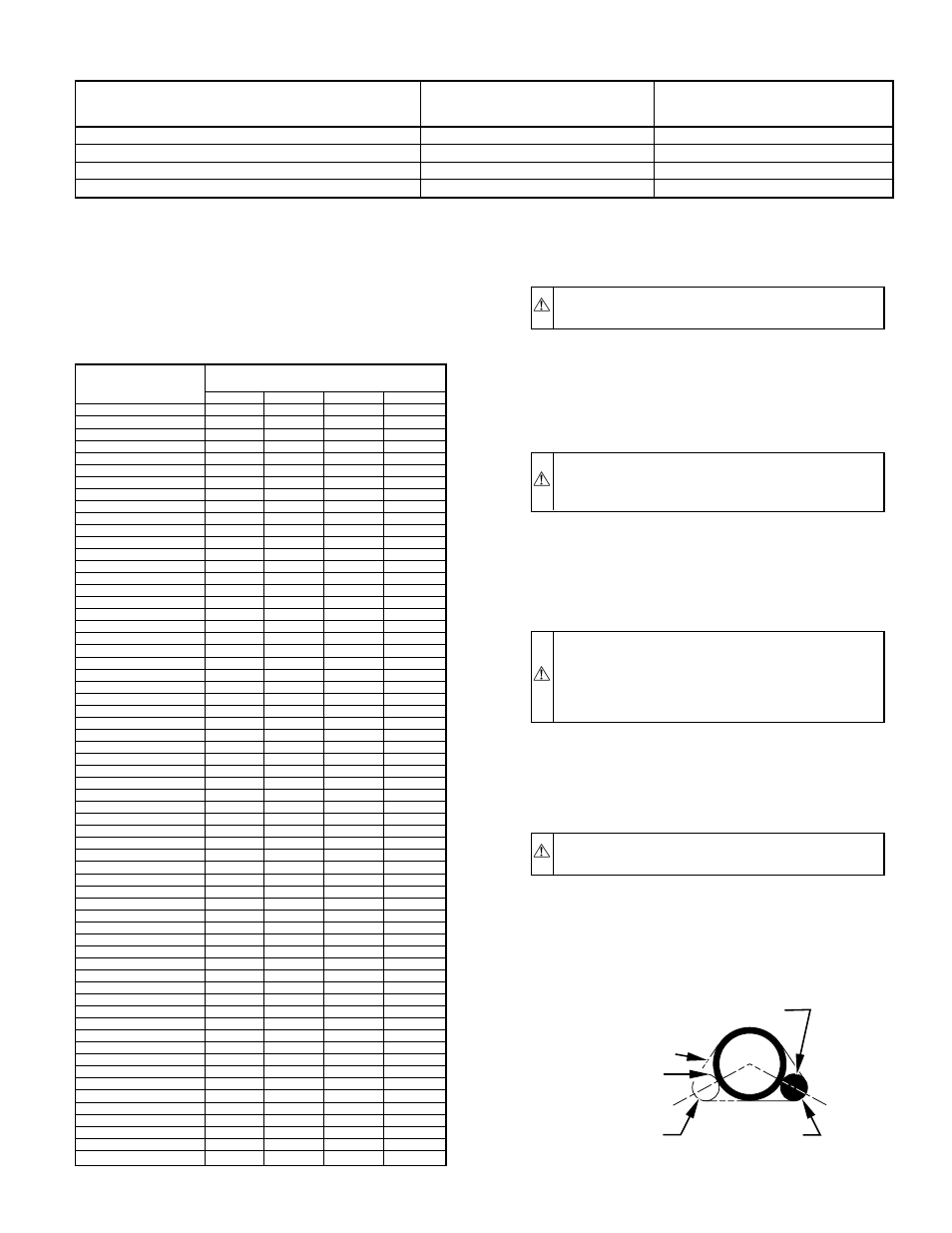
SENSING BULB
STRAP
8 O'CLOCK
4 O'CLOCK
SUCTION
TUBE
A02000
Fig. 7—Positioning of Sensing Bulb
—5—