Service (cont.), Wiring diagrams – Bunn AFPO-2 User Manual
Page 16
16
SERVICE (cont.)
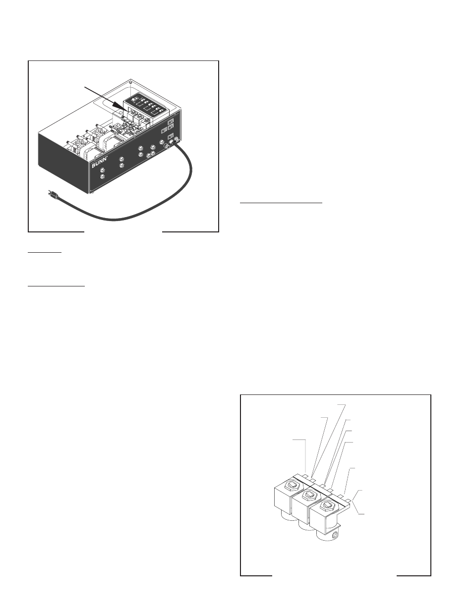
SOLENOIDS
FIG. 16 SOLENOIDS
Location:
The solenoids are located inside the autofill box.
Test Procedure:
1. Disconnect the dispenser from the power source.
2. Disconnect the white/violet, violet or blue wire and
the white wire from the solenoid.
3. Connect the dispenser to the power source. Press
the solenoid (water) switch, and with a voltmeter,
check the voltage between the white wire, and
either the blue, violet, or white/violet wire. The
indication must be:
a) 120 volts ac for two wire 120 volt models.
b) 200 to 240 volts ac for two wire 200 or 240 volt
models.
c) 230 volts ac for two wire 230 volt models.
4. Disconnect the dispenser from the power source.
If voltage is present as described, proceed to #5.
If voltage is not present as described, refer to the
Wiring Diagrams
and check dispenser wiring harness.
5. Check for continuity across the solenoid valve coil
terminals.
If continuity is present as described, refer to Fig. 17
and reconnect the wires to the solenoid.
If continuity is not present as described, replace the
solenoid valve.
FIG. 17 SOLENOID TERMINALS
P1521
P1544
FL
AV
OR
IN
PU
T
1
2
W
AT
ER
IN
PU
T
RE
FIL
L
MA
IN
PO
W
ER
2
1
1
2
3
3
3
FL
AV
OR
OU
TP
UT
FL
AV
OR
OU
TP
UT
W
AT
ER
OU
TP
UT
FL
AV
OR
OU
TP
UT
W
AT
ER
OU
TP
UT
W
AT
ER
OU
TP
UT
6. Check the solenoid valve for coil action. Connect
the dispenser to the power source. Press the
solenoid (water) switch and listen carefully in the
vicinity of the solenoid valve for a "clicking" sound
as the coil magnet attracts.
7. Disconnect the dispenser from the power source.
If the sound is heard as described and water will not
pass through the solenoid valve, there may be a
blockage in the water inlet before the solenoid valve or,
the solenoid valve may require inspection for wear,
and removal of waterborne particles.
If the sound is not heard as described, rebuild or
replace the solenoid valve.
Solenoid Valve Repair:
1. Remove the wires from the solenoid valve to be
repaired.
2. Turn off the water supply to the dispenser.
3. Remove the nut securing solenoid valve coil to the
base.
4. Remove guide, washer, o-ring, plunger/spring
and inspect for wear. Replace parts as required.
5. Install new o-ring in the solenoid valve base.
6. Install plunger/spring in the guide with spring to
the bottom of the guide.
7. Install guide with the plunger/spring into the sole-
noid valve base.
8. Install washer on guide.
9. Install coil with retainer on guide and secure with
nut.
10. Refer to Fig. 17 and reconnect the wires.
#1 AFPO-2
& 3 #2 AFPO-2
& 3 #3 AFPO-3
ONLY
WHI from Main Harness
WHI to Solenoid #2
BLU from Solenoid
Switch #1
WHI to Solenoid #1
WHI to Pump #1
VIO from Solenoid
Switch #2
WHI/VIO from
Solenoid Switch #3
WHI to Main
Harness
WHI to Pump #3
28791 040501