Model 361aan upflow-horizontal oil furnace, Specifications – Bryant Oil Fired 363AAP 361AAN User Manual
Page 2
—2—
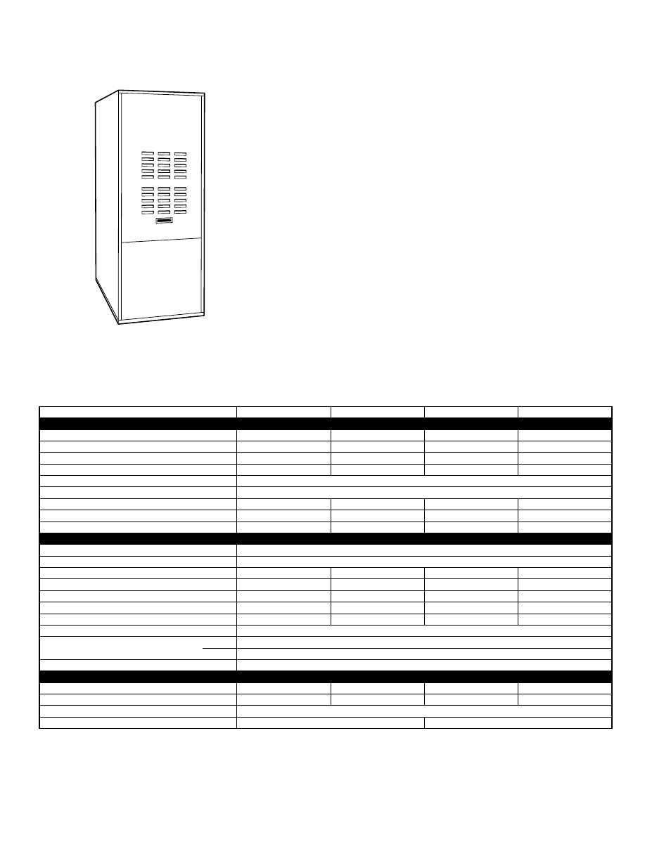
MODEL 361AAN UPFLOW-HORIZONTAL OIL FURNACE
A93211
The 361AAN Furnace is designed for top performance to provide years of reli-
able, comfortable home heating.
The 361AAN is an upflow/horizontal oil furnace that can be installed upflow, hor-
izontal right, or horizontal left for greater application coverage. The flue exits the
front of the furnace. The heat exchanger is backed by a Limited Lifetime Warranty.
FEATURES
INSTALLATION FLEXIBILITY
—The 361AAN installs in upflow, horizontal right,
or horizontal left positions for greater application coverage and installation flexi-
bility.
HEAT EXCHANGER
—The stainless steel primary and aluminized steel second-
ary heat exchangers are designed for outstanding reliability backed by a Limited
Lifetime Warranty. The heat exchanger utilizes crimped seams instead of welds
for corrosion resistance. All internal surfaces are accessible for any field mainte-
nance without removing the heat exchanger.
CLEANOUT PORTS
—Allow easy cleaning of secondary heat exchanger tubes
without disassembly of the furnace or heat exchanger.
CONTROLS
—The Beckett oil burner is equipped with an electronic primary relay
for added reliability. Integrated fan timer control board with low-voltage terminal
strip and 40-va transformer make air conditioning installation easy.
HEAVY DUTY BLOWER
—Blower motors are PSC type and 3 speed. The direct-
drive blowers eliminate belt adjustments in the field. The constant low-speed
blower switch provides air circulation during “off” cycles for indoor air filtration.
DURABLE CABINET
—The casing is constructed of prepainted steel for years of
attractiveness. Filter and filter rack are provided with each furnace.
SPECIFICATIONS
* Capacity and AFUE in accordance with U.S. Government DOE test procedures.
† Permissible limits of the voltage range at which the unit will operate satisfactorily.
‡ Length shown is measured 1 way along wire path between unit and service panel for maximum 2% voltage drop.
** Time-delay fuse is recommended.
ICS—Isolated Combustion System
UNIT SIZE
036075
036105
048125
060155
RATINGS AND PERFORMANCE
Firing Rate
0.50
0.76
0.90
1.12
Input (Btuh)
72,000
105,000
125,000
154,000
Heating Capacity (Btuh)*
55,000
85,000
100,000
125,000
AFUE %*
ICS
80.0
80.7
81.5
80.3
Oil Pump Stages
1
Heating Temperature Rise
°
F
55—85
Recommended Heating Blower Speed
Low
Medium
Medium
High
Cooling CFM @ 0.5-in. wc Static Pressure
1255
1365
1745
1935
Heating CFM @ 0.2-in. wc Static Pressure
850
1425
1645
2170
ELECTRICAL
Unit Volts—Hertz—Phase
115—60—1
Operating Voltage Range†
104—127
Rated Load Amps
12.55
12.55
15.65
16.15
Minimum Ampacity for Wire Sizing
14
14
18
19
Minimum Wire Size AWG
14
14
12
12
Maximum Wire Length (Ft)‡
26
26
32
30
Maximum Fuse Size (Amps)**
15
15
20
20
Control Transformer (24v)
40va
External Control Power Available
Heating
35va
Cooling
35va
Burner Model (3450 RPM)
Beckett AFG
BLOWER DATA
Motor HP
1/3
1/3
1/2
3/4
Blower Wheel Size (In.)
10 x 9
10 x 9
12 x 9
12 x 12
Blower Motor Speed and Type
1075 PSC Direct
Filter Quantity and Size
(1) 20-1/8 x 25 x 1
(1) 20-1/8 x 30 x 1