Bryant AIR CONDITIONERS 564A User Manual
Page 16
Inspect the drain pan and condensate drain line when inspecting
the coils. Clean the drain pan and condensate drain by removing all
foreign matter from the pan. Flush the pan and drain tube with
clear water. Do not splash water on the insulation, motor, wiring,
or air filter(s). If the drain tube is restricted, clear it with a
‘‘plumbers snake’’ or similar probe device. Ensure that the
auxiliary drain port above the drain tube is also clear.
V.
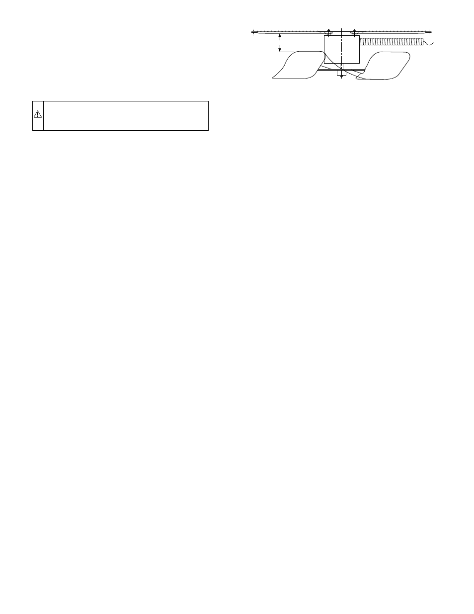
CONDENSER FAN
CAUTION:
Keep the condenser fan free from all ob-
structions to ensure proper cooling operation. Never place
articles on top of the unit. Damage to unit may result.
1. Shut off unit power supply.
2. Remove condenser-fan assembly (grille, motor, motor
cover, and fan) by removing screws and flipping assembly
onto unit top cover.
3. Loosen fan hub setscrews.
4. Adjust fan height as shown in Fig. 21.
5. Tighten setscrews.
6. Replace condenser-fan assembly.
VI.
ELECTRICAL CONTROLS AND WIRING
Inspect and check the electrical controls and wiring annually. Be
sure to turn off the electrical power to the unit.
Remove the top panel to locate all the electrical controls and
wiring. Check all electrical connections for tightness. Tighten all
screw connections. If any smoky or burned connections are
noticed, disassemble the connection, clean all the parts, restrip the
wire end and reassemble the connection properly and securely.
After inspecting the electrical controls and wiring, replace all the
panels. Start the unit, and observe at least one complete cooling
cycle to ensure proper operation. If discrepancies are observed in
operating cycle, or if a suspected malfunction has occurred, check
each electrical component with the proper electrical instrumenta-
tion. Refer to the unit wiring label when making these checkouts.
NOTE:
Refer to the Sequence of Operation section on page 14, as
an aid in determining proper control operation.
VII.
REFRIGERANT CIRCUIT
Inspect all refrigerant tubing connections and the unit base for oil
accumulations annually. Detecting oil generally indicates a refrig-
erant leak.
If oil is detected or if low cooling performance is suspected,
leak-test all refrigerant tubing using an electronic leak-detector, or
liquid-soap solution. If a refrigerant leak is detected, refer to Check
for Refrigerant Leaks section on page 11.
If no refrigerant leaks are found and low cooling performance is
suspected, refer to Refrigerant Charge section on page 11.
VIII.
EVAPORATOR AIRFLOW
The cooling airflow does not require checking unless improper
performance is suspected. If a problem exists, be sure that all
supply- and return-air grilles are open and free from obstructions,
and that the air filter is clean. When necessary, refer to Indoor
Airflow and Airflow Adjustments section on page 14 to check the
system airflow.
IX.
METERING DEVICES
Refrigerant metering devices are fixed orifices and are located in
the inlet header to the evaporator coil.
X.
LIQUID LINE STRAINER
The liquid line strainer (to protect metering device) is made of wire
mesh and is located in the liquid line on the inlet side of the
metering device.
Fig. 21—Condenser-Fan Adjustment
C00021
3.125 in.
—16—