Bryant AIR CONDITIONERS 564A User Manual
Page 15
3. Inspect blower motor and wheel for cleanliness each
cooling season. Clean when necessary. For first heating
season, inspect blower wheel bimonthly to determine
proper cleaning frequency.
4. Check electrical connections for tightness and controls for
proper operation each cooling season. Service when neces-
sary.
5. Check the drain channel in the top cover periodically for
blockage (leaves, insects). Clean as needed.
WARNING:
Failure to follow these warnings could
result in serious injury or death:
1. Turn off electrical power to the unit before performing
any maintenance or service on the unit.
2. Use extreme caution when removing panels and parts.
As with any mechanical equipment, personal injury
can result from sharp edges, etc.
3. Never place anything combustible either on, or in
contact with, the unit.
I.
AIR FILTER
NEVER OPERATE THE UNIT WITHOUT A SUITABLE AIR
FILTER IN THE RETURN-AIR DUCT SYSTEM. ALWAYS
REPLACE THE FILTER WITH THE SAME DIMENSIONAL
SIZE AND TYPE AS ORIGINALLY INSTALLED. SEE
TABLE 1 FOR RECOMMENDED FILTER SIZES.
Inspect air filter(s) at least once each month and replace
(throwaway-type) or clean (cleanable-type) at least twice during
each cooling season or whenever the filters become clogged with
dust and lint.
Replace filters with the same dimensional size and type as
originally provided, when necessary.
II.
UNIT TOP REMOVAL (CONDENSER-COIL SIDE)
NOTE:
When performing maintenance or service procedures that
require removal of the unit top, be sure to perform all of the routine
maintenance procedures that require top removal, including coil
inspection and cleaning, and condensate drain pan inspection and
cleaning.
WARNING:
Disconnect and tag electrical power to the
unit before removing top. Failure to adhere to this
warning could cause serious injury or death.
Only qualified service personnel should perform maintenance and
service procedures that require unit top removal.
Refer to the following top removal procedures:
1. Remove 7 screws on unit top cover surface. (Save all
screws.)
2. Remove 2 screws on unit top cover flange. (Save all
screws.)
3. Lift top from unit carefully. Set top on edge and make sure
that top is supported by unit side that is opposite duct (or
plenum) side.
4. Carefully replace and secure unit top to unit, using screws
removed in Steps 1 and 2, when maintenance and/or service
procedures are completed.
III.
EVAPORATOR BLOWER AND MOTOR
For longer life, operating economy, and continuing efficiency,
clean accumulated dirt and grease from the blower wheel and
motor annually.
WARNING:
Disconnect and tag electrical power to the
unit before cleaning the blower wheel. Failure to adhere
to this warning could cause serious injury or death.
To clean the blower wheel:
1. Access the blower assembly as follows:
a. Remove top access panel.
b. Remove 3 screws that hold blower orifice ring to blower
housing. Save screws.
c. Loosen setscrew(s) which secure wheel to motor shaft.
2. Remove and clean blower wheel as follows:
a. Lift wheel from housing. When handling and/or cleaning
blower wheel, be sure not to disturb balance weights
(clips) on blower wheel vanes.
b. Remove caked-on dirt from wheel and housing with a
brush. Remove lint and/or dirt accumulations from
wheel and housing with vacuum cleaner, using a soft
brush attachment. Remove grease and oil with a mild
solvent.
c. Reassemble blower into housing. Place upper orifice ring
on blower to judge location of the blower wheel. Blower
wheel should be approximately 0.2-in. below bottom of
orifice ring when centered correctly. Be sure setscrews
are tightened on motor and are not on round part of shaft.
d. Set upper orifice ring in place with 3 screws removed in
step 1.
e. Replace top access panel.
IV.
CONDENSER COIL, EVAPORATOR COIL, AND
CONDENSATE DRAIN PAN
Inspect the condenser coil, evaporator coil, and condensate drain
pan at least once each year. Proper inspection and cleaning
requires the removal of the unit top. See Unit Top Removal section
above.
The coils are easily cleaned when dry; therefore, inspect and clean
the coils either before or after each cooling season. Remove all
obstructions (including weeds and shrubs) that interfere with the
airflow through the condenser coil. Straighten bent fins with a fin
comb. If coated with dirt or lint, clean the coils with a vacuum
cleaner, using a soft brush attachment. Be careful not to bend the
fins. If coated with oil or grease, clean the coils with a mild
detergent-and-water solution. Rinse coils with clear water, using a
garden hose. Be careful not to splash water on motors, insulation,
wiring, or air filter(s). For best results, spray condenser-coil fins
from inside to outside the unit. On units with an outer and inner
condenser coil, be sure to clean between the coils. Be sure to flush
all dirt and debris from the unit base.
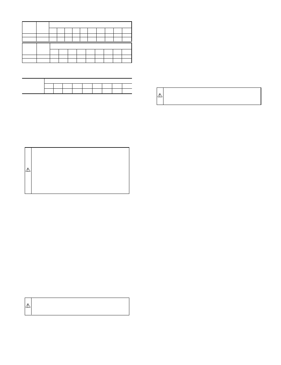
TABLE 6—FILTER PRESSURE DROP (IN. WG)
UNIT
SIZE
564A
FILTER
SIZE
(IN.)
CFM
500 600 700 800 900 1000 1100 1200 1300 1400
024-042 24 x 24 0.06 0.07 0.08 0.08 0.09 0.09 0.09 0.10 0.11 0.12
048,060 24 x 30
-
-
-
-
-
-
-
-
0.08 0.09
UNIT
SIZE
564A
FILTER
SIZE
(IN.)
CFM
1500 1600 1700 1800 1900 2000 2100 2200 2300
024-042 24 x 24 0.14 0.15
-
-
-
-
-
-
-
048,060 24 x 30 0.10 0.11 0.12 0.13 0.14 0.15 0.16 0.17 0.18
TABLE 7—ACCESSORY ELECTRIC HEAT PRESSURE
DROP (IN. WG)
HEATER KW
5-20
CFM
600
800
1000 1200 1400 1600 1800 2000 2200
0.06 0.08
0.10
0.13
0.15
0.18
0.20
0.23
0.25
—15—