Bryant AIR CONDITIONERS 564A User Manual
Page 14
MAINTENANCE
To ensure continuing high performance, and to reduce the possi-
bility of premature equipment failure, periodic maintenance must
be performed on this equipment. This cooling unit should be
inspected at least once each year by a qualified service person. To
troubleshoot cooling of units, refer to Troubleshooting chart in
back of book.
NOTE TO EQUIPMENT OWNER: Consult your local dealer
about the availability of a maintenance contract.
WARNING:
The ability to properly perform mainte-
nance on this equipment requires certain expertise, me-
chanical skills, tools and equipment. If you do not possess
these, do not attempt to perform any maintenance on this
equipment, other than those procedures recommended in
the User’s Manual. FAILURE TO HEED THIS WARN-
ING COULD RESULT IN SERIOUS INJURY, DEATH
OR DAMAGE TO THIS EQUIPMENT.
The minimum maintenance requirements for this equipment are as
follows:
1. Inspect air filter(s) each month. Clean or replace when
necessary.
2. Inspect indoor coil, outdoor coil, drain pan, and condensate
drain each cooling season for cleanliness. Clean when
necessary.
→
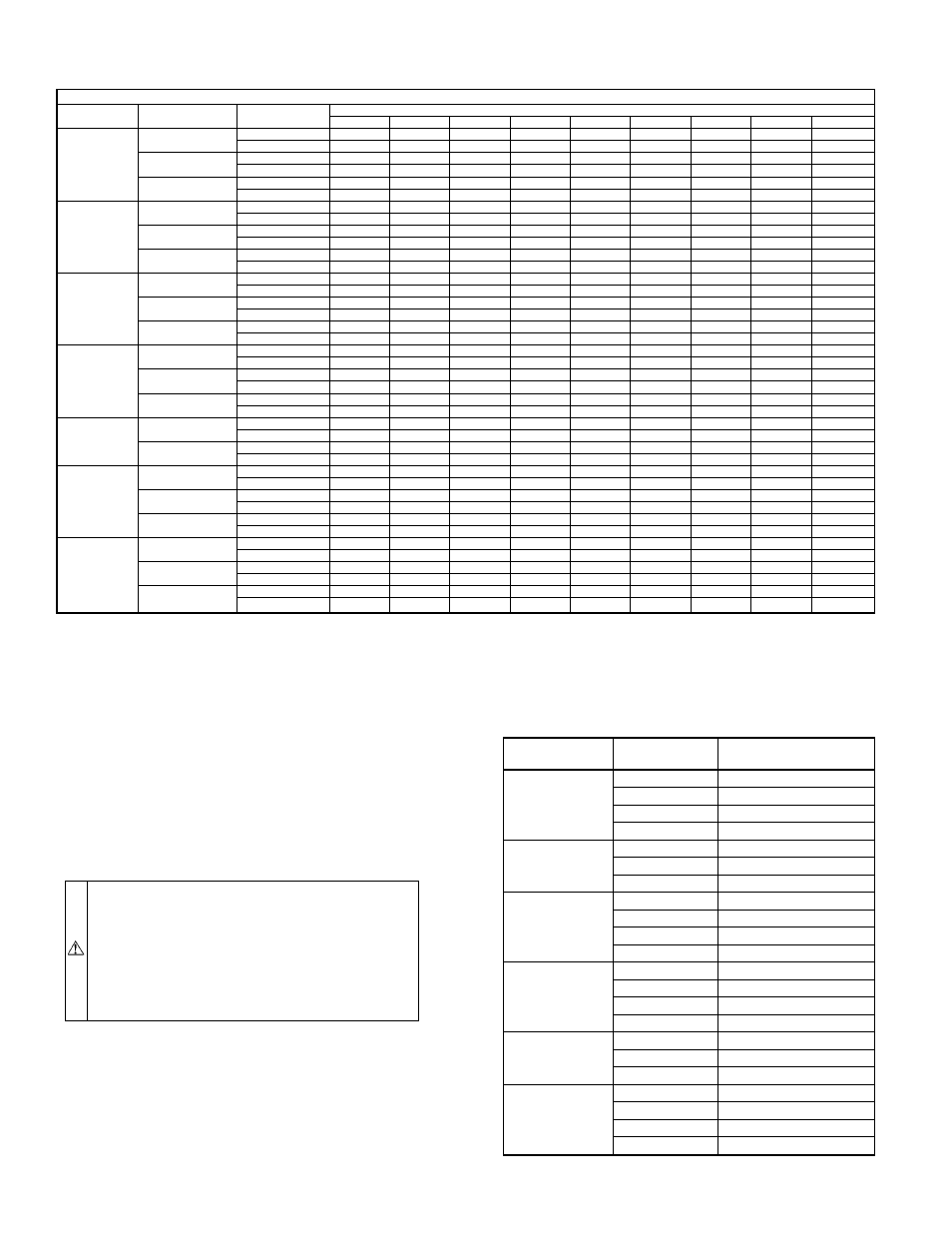
TABLE 4—DRY COIL AIR DELIVERY* HORIZONTAL DISCHARGE
(DEDUCT 10% FOR 208 VOLT OPERATION)
230 AND 460 VOLT
Unit
Motor Speed
Air Delivery
External Static Pressure (in. wg)
0.1
0.2
0.3
0.4
0.5
0.6
0.7
0.8
0.9
024
Low
Watts
288
285
282
279
274
268
261
-
-
Cfm
875
820
802
734
668
582
478
-
-
Med
Watts
390
383
378
369
360
350
340
-
-
Cfm
1131
1090
1038
978
917
830
721
-
-
High
Watts
528
520
510
495
480
460
450
-
-
Cfm
1391
1338
1285
1200
1115
1018
920
-
-
030
Low
Watts
288
285
282
279
274
268
261
-
-
Cfm
875
820
802
734
668
582
478
-
-
Med
Watts
390
383
378
369
360
350
340
-
-
Cfm
1131
1090
1038
978
917
830
721
-
-
High
Watts
528
520
510
495
480
460
450
-
-
Cfm
1891
1338
1285
1200
1115
1018
920
-
-
036
Low
Watts
450
435
420
400
380
335
326
311
-
Cfm
1231
1218
1204
1120
1008
950
863
751
-
Med
Watts
470
450
445
410
388
359
338
321
-
Cfm
1302
1264
1205
1163
1081
940
873
783
-
High
Watts
660
635
610
575
540
505
485
460
-
Cfm
1700
1660
1581
1450
1297
1190
1095
999
-
042
Low
Watts
478
458
440
411
378
350
327
317
-
Cfm
1303
1270
1224
1179
1126
1022
911
816
-
Med
Watts
481
468
450
438
404
370
338
320
735
Cfm
1310
1280
1241
1181
1110
1022
943
811
-
High
Watts
-
798
678
647
618
578
540
500
-
Cfm
-
1736
1688
1618
1510
1421
1309
1187
1060
048
Low
Watts
-
-
801
760
730
688
650
600
570
Cfm
-
-
1898
1841
1757
1682
1564
1429
1365
High
Watts
-
-
870
842
818
782
696
632
628
Cfm
-
-
2000
1903
1799
1718
1625
1446
1333
060†
2 Speed
Low
Watts
890
850
810
790
735
680
580
480
422
Cfm
1834
1820
1791
1762
1703
1640
1415
1159
950
Med
Watts
1040
1018
1000
950
890
835
790
650
580
Cfm
2230
2102
2025
1960
1901
1855
1752
1468
1121
High
Watts
1073
1038
1001
958
896
840
800
691
575
Cfm
2230
2202
2160
2122
2052
1926
1791
1588
1202
060
3 Speed
Low
Watts
1058
1008
942
891
860
828
750
700
630
Cfm
2384
2200
2197
2071
1989
1889
1820
1729
1640
Med
Watts
1266
1086
1021
1002
977
924
860
819
700
Cfm
2724
2476
2392
2344
2262
2132
2001
1910
1820
High
Watts
1301
1216
1197
1127
1058
1011
979
869
870
Cfm
2760
2618
2543
2423
2292
2169
2056
1943
1832
* Air delivery values are based on operating voltage of 230 v or 460 v, dry coil, without filter or electric heater. Deduct wet coil, filter and electric heater pressure drops to
obtain external static pressure available for ducting.
See Tables 5-7.
→
†460-v motors have 2 or 3 speeds (size 060 only).
NOTES:
1. Do not operate the unit at a cooling airflow that is less than 350 cfm for each 12,000 Btuh of rated cooling capacity. Evaporator coil frosting may occur at airflows below
this point.
2. Dashes indicate portions of the table that are beyond the blower motor capacity or are not recommended.
TABLE 5—WET COIL PRESSURE DROP
UNIT SIZE
564A
AIRFLOW
(CFM)
PRESSURE DROP
(IN. WG)
024
600
0.02
700
0.05
800
0.06
900
0.07
030
900
0.06
1000
0.06
1200
0.08
036
1000
0.07
1200
0.09
1400
0.11
1600
0.12
042
1000
0.04
1200
0.06
1400
0.08
1600
0.09
048
1400
0.07
1600
0.08
1800
0.09
060
1700
0.07
1800
0.08
2100
0.09
2300
0.10
—14—