Warning, Start--up, Step 1 — check for refrigerant leaks – Bryant 574D User Manual
Page 13: Step 2 — start--up heating and make adjust- ments
13
FIRE, EXPLOSION HAZARD
Failure to follow this warning could result in personal
injury, death or property damage.
Do not purge gas supply into the combustion chamber. Do
not use a match or other open flame to check for gas leaks.
!
WARNING
4. Verify the following conditions:
a. Make sure gas line is free of air. Before lighting the unit
for the first time, perform the following with the gas
valve in the OFF position:
NOTE: If the gas supply pipe was not purged before connecting
the unit, it will be full of air. It is recommended that the ground
joint union be loosened, and the supply line be allowed to purge
until the odor of gas is detected. Never purge gas lines into a
combustion chamber. Immediately upon detection of gas odor,
retighten the union. Allow 5 minutes to elapse, then light unit.
b. Make sure that condenser--fan blade is correctly
positioned in fan orifice. Top 1/3 of condenser--fan
blade should be within fan orifice venturi.
c. Ensure fan hub is positioned correctly with respect to
motor housing (See Fig. 12).
d. Make sure that air filter(s) is in place.
e. Make sure that condensate drain trap is filled with water
to ensure proper drainage.
f. Make sure that all tools and miscellaneous loose parts
have been removed.
FAN GRILLE
MOTOR
1/8" MAX BETWEEN
MOTOR AND FAN HUB
MOTOR SHAFT
1/2ý
C99009
Fig. 12 -- Fan Blade Clearance
START--UP
Step 1 — Check for Refrigerant Leaks
Proceed as follows to locate and repair a refrigerant leak and to
charge the unit:
1. Locate leak and make sure that refrigerant system pressure
has been relieved and reclaimed from both high-- and
low--pressure ports.
2. Repair leak following accepted practices.
NOTE: Install a filter drier whenever the system has been opened
for repair.
3. Add a small charge of Puron (R--410A) refrigerant vapor to
system and leak--test unit.
4. Recover refrigerant from refrigerant system and evacuate to
500 microns if no additional leaks are found.
5. Charge unit with Puron (R--410A) refrigerant, using a
volumetric charging cylinder or accurate scale. Refer to unit
rating plate for required charge.
Step 2 — Start--up Heating and Make Adjust-
ments
Complete the required procedures given in the Pre--Start--Up
section before starting the unit. Do not jumper any safety devices
when operating the unit. Make sure that burner orifices are
properly aligned. Unstable operation my occur when the burner
orifices in the manifold are misaligned.
Follow the lighting instructions on the heating section operation
label (located inside the burner or blower access door) to start the
heating section.
NOTE: Make sure that gas supply has been purged, and that all
gas piping has been checked for leaks.
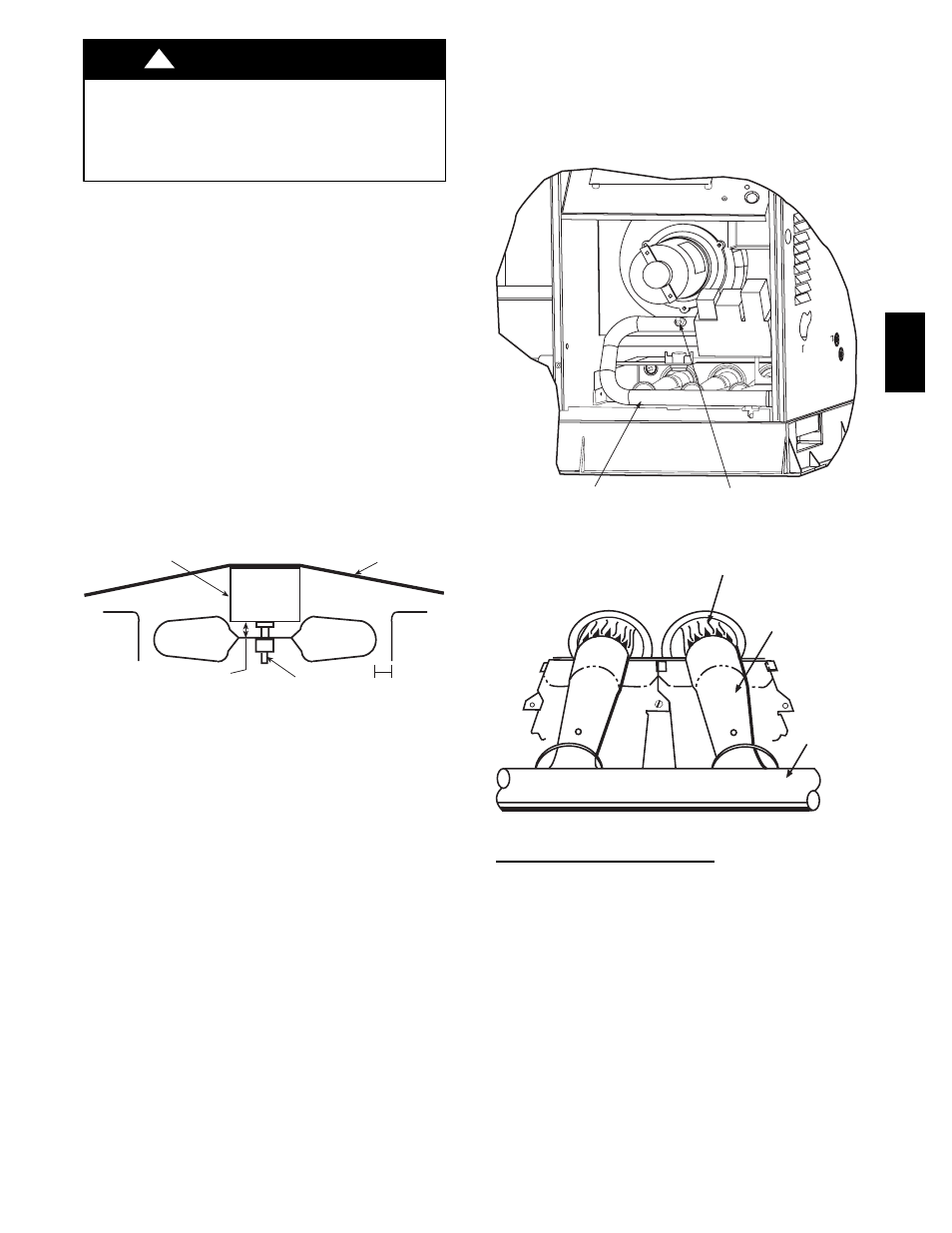
MANIFOLD
PIPE PLUG
C99019
Fig. 13 -- Burner Assembly
MANIFOLD
BURNER
BURNER FLAME
C99021
Fig. 14 -- Monoport Burner
CHECK HEATING CONTROL
Start and check the unit for proper heating control operation as
follows (see furnace lighting instructions located inside burner or
blower access panel):
1. Place room thermostat SYSTEM switch in the HEAT
position and the fan switch is placed in AUTO position.
2. Set the heating temperature control of the thermostat above
room temperature.
3. The induced--draft motor will start.
4. After a call for heating, the main burner should light within
5 sec. If the burners do not light, there is a 22--sec. delay
before another 5--sec. try. If the burners still do not light,
this sequence is repeated. If the burners do not light within
15 minutes from the initial call for heat, there is a lockout.
To reset the control, break the 24--v power to W.
5. The evaporator fan will turn on 45 sec. after the flame has
been established. The evaporator fan will turn off 45 sec.
after the thermostat has been satisfied.
574D