Bryant GAMA 331JAV User Manual
Page 9
A terminal block (EAC-1 [hot] and EAC-2 [neutral]) is
provided for EAC connection. (See Fig. 10.) The terminals
are energized with 115v, 1-amp maximum during blower
motor operation.
2. Humidifier (HUM)
Screw terminals (HUM-1 and C
OM
) are provided for 24-v
humidifier connection. The terminals are energized with
24v, 0.5-amp maximum when the gas valve is energized.
VII. VENTING
Refer to National or Local Installation Code such as; National Fuel
Gas Code NFPA No. 54-1996/Z223.1-1996, or the Canadian
Installation Code, CAN B149.1- and .2-M95, for proper vent
sizing and installation requirements. Use enclosed Venting Tables
for Category I Fan-Assisted Furnaces for quick, easy reference.
The horizontal portion of the venting system shall maintain a
minimum of 1/4-in. upward slope per linear ft, and it shall be
rigidly supported every 5 ft or less with hangers or straps to ensure
that there will be no movement after installation.
VIII. START-UP, ADJUSTMENT, AND SAFETY CHECK
A. General
The furnace must have a 115-v power supply properly connected
and grounded. Correct polarity must be maintained to enable gas
heating operation.
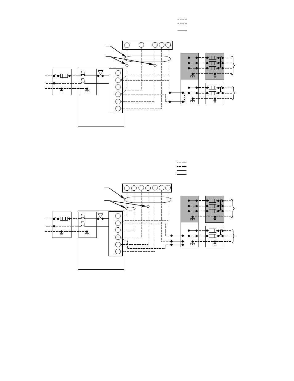
→ Fig. 11—Heating and Cooling Application Wiring Diagram With 1-Stage Thermostat and Condensing Unit
A97443
115-V FUSED
DISCONNECT
SWITCH
(WHEN REQUIRED)
JUNCTION
BOX
CONTROL
BOX
24-V
TERMINAL
BLOCK
TWO-WIRE
HEATING-
ONLY
FIVE
WIRE
1-STAGE THERMOSTAT TERMINALS
FIELD-SUPPLIED
FUSED DISCONNECT
CONDENSING
UNIT
FURNACE
COM
R
W
Y
R
G
C
GND
GND
FIELD 24-V WIRING
FIELD 115-, 208/230-, 460-V WIRING
FACTORY 24-V WIRING
FACTORY 115-V WIRING
208/230- OR
460-V
THREE
PHASE
208/230-V
SINGLE
PHASE
WHT
BLK
WHT
BLK
W/W1
W2
Y/Y2
G
NOTES:
1. Connect Y-terminal as shown for proper operation.
2. Some thermostats require a "C" terminal connection as shown.
3. If any of the original wire, as supplied, must be replaced,
use same type or equivalent wire.
→ Fig. 12—Heating and Cooling Application Diagram With 2-Stage Thermostat and Condensing Unit
A97444
115-V FUSED
DISCONNECT
SWITCH
(WHEN REQUIRED)
JUNCTION
BOX
CONTROL
BOX
24-V
TERMINAL
BLOCK
THREE-WIRE
HEATING-
ONLY
SEVEN
WIRE
2-STAGE THERMOSTAT TERMINALS
FIELD-SUPPLIED
FUSED DISCONNECT
2-SPEED
CONDENSING
UNIT
FURNACE
G
R
W2
Y2
G
Y1
C
GND
GND
FIELD 24-V WIRING
FIELD 115-, 208/230-, 460-V WIRING
FACTORY 24-V WIRING
FACTORY 115-V WIRING
208/230- OR
460-V
THREE
PHASE
208/230-V
SINGLE
PHASE
Y2
Y1
C
WHT
BLK
WHT
BLK
W1
R
W2
COM
W/W1
Y/Y2
NOTES:
1. Connect Y-terminal as shown for proper operation.
2. Some thermostats require a "C" terminal connection as shown.
3. If any of the original wire, as supplied, must be replaced,
use same type or equivalent wire.
—9—
→