Bryant GAMA 331JAV User Manual
Page 5
c. If furnace is installed to obtain return air is taken directly
from hallway or space adjacent to furnace, all air for
combustion must come from outdoors.
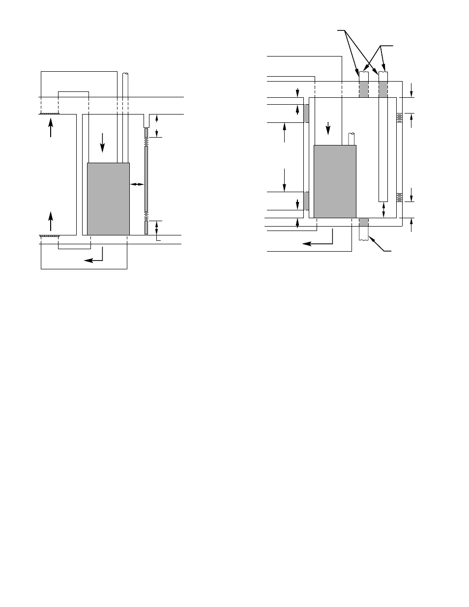
2. Air from outside the structure requires 1 of the following
methods:
a. If combustion air is taken from outdoors through 2
vertical ducts, the openings and ducts MUST have at
least 1 sq in. of free area per 4000 Btuh of total input for
all equipment within the confined space. (See Fig. 4 and
Table 2.)
b. If combustion air is taken from outdoors through 2
horizontal ducts, the openings and ducts MUST have at
least 1 sq in. of free area per 2000 Btuh of total input for
all equipment within the confined space. (See Fig. 4 and
Table 2.)
c. If combustion air is taken from outdoors through a single
opening or duct (horizontal or vertical) commencing
within 12 in. of the top of the confined space, opening
and duct MUST have at least 1 sq in. of free area per
3000 Btuh of the total input for all equipment within the
confined space and not less than the sum of the areas of
all vent connectors in the confined space. (See Fig. 4 and
Table 2.) Equipment clearances to the structure shall be
at least 1 in. from the sides and back and 6 in. from the
front of the appliances.
When ducts are used, they must be of the same cross-sectional area
as the free area of the openings to which they connect. The
minimum dimension of ducts must not be less than 3 in. (See Fig.
4.)
III. SUPPLY-AIR PLENUM INSTALLATION (DOWN-
FLOW)
A. Downflow Installation
NOTE: This furnace is approved for use on combustible flooring
when
manufacturer’s
accessory
floor
base
Part
No.
KGASB0201ALL is used. Manufacturer’s accessory floor base is
not required when this furnace is installed on manufacturer’s Coil
Assembly Part No. CD5 or CK5, or Coil Box Part No. KCAKC is
used.
1. Determine application being installed from Table 3.
2. Construct hole in floor per dimensions specified in Table 3
and Fig. 5.
3. Construct plenum to dimensions specified in Table 3.
4. If downflow subbase (KGASB) is used, install as shown in
Fig. 6.
If coil assembly CD5, CK5, or Coil Box KCAKC is used,
install as shown in Fig. 7.
B. Installation On Combustible Floor
1. Cut and frame hole in floor per dimensions in Installation
Instructions packaged with downflow subbase.
2. When completed, downflow subbase, plenum, and furnace
(or coil casing when used) should be installed as shown in
Fig. 6.
Fig. 3—Confined Space: Air for Combustion and Ventilation
from an Unconfined Space
A93387
RETURN
AIR
6″ MIN
(FRONT)
†
SUPPLY AIR
VENT THROUGH ROOF
(CATEGORY I)
1 SQ IN.
PER 1000
BTUH* IN DOOR
OR WALL
12″ MAX
1 SQ IN.
PER 1000
BTUH* IN DOOR
OR WALL
12″ MAX
INTERIOR
HEATED
SPACE
* Minimum opening size is 100 sq in. with
minimum dimensions of 3 in.
†
Minimum of 3 in. when type B-1 vent is used.
UNCONFINED
SPACE
Fig. 4—Confined Space: Air for Combustion and Ventilation
from Outdoors
A93388
DUCTS TO
OUTDOORS
1 SQ IN.
PER 4000
BTUH
*
RETURN
AIR
VENT
THROUGH
ROOF
(CATEGORY I)
D
B
A
C
E
1 SQ IN.
PER 4000
BTUH
DUCT
TO
OUTDOORS
SUPPLY AIR
1 SQ IN.
PER 2000
BTUH*
DUCTS
TO
OUTSIDE
12″ MAX
12″ MAX
CONFINED
SPACE
12″
MAX
12″
MAX
1 SQ IN.
PER 4000
BTUH
*
OUTDOORS
1 SQ IN.
PER 4000
BTUH
*
1 SQ IN.
PER 2000
BTUH*
12″ MAX
Use any of the following
combinations of openings:
A & B C & D D & E F & G
NOTE:
*Minimum dimensions of 3 in.
F
G
—5—
→