Bryant GAMA 331JAV User Manual
Page 8
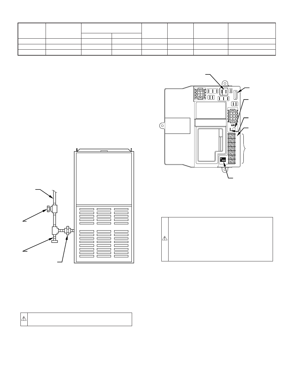
Install accessible manual shutoff valve upstream of furnace gas
controls and within 72 in. of furnace. A 1/8-in. NPT plugged
tapping is provided on gas value for test gage connection.
Installation of additional 1/8-in. NPT plugged tapping, accessible
for test gage connection, installed immediately upstream of gas
supply connection to furnace and downstream of manual shutoff
valve is not required. Place ground joint union between gas control
manifold and manual shutoff.
Install sediment trap in riser leading to furnace. The trap can be
installed by connecting a tee to riser leading from furnace. Connect
capped nipple into lower end of tee. The capped nipple should
extend below level of gas controls. (See Fig. 9.)
After all connections have been made, purge lines and check for
gas leakage with regulated gas supply pressure.
VI. ELECTRICAL CONNECTIONS
A. 115-v Wiring
Refer to unit rating plate or Table 5 for equipment electrical
requirements. The control system requires an earth ground for
proper operation.
CAUTION: Do not connect aluminum wire between
disconnect switch and furnace. Use only copper wire.
Make all electrical connections in accordance with the current
edition of the National Electrical Code (NEC) ANSI/NFPA
70-1996 and any local codes or ordinances that might apply. For
Canadian installations, all electrical connections must be made in
accordance with CSA C22.1 Canadian Electrical Code or authori-
ties having jurisdiction.
NOTE: Proper polarity must be maintained for 115-v wiring. If
polarity is incorrect, the furnace control status LED will flash
rapidly and prevent heating operation.
WARNING: The cabinet must have an uninterrupted or
unbroken ground according to NEC ANSI/NFPA 70-
1996 and Canadian Electrical Code CSA C22.1 or local
codes to minimize personal injury if an electrical fault
should occur. This may consist of electrical wire or
conduit approved for electrical ground when installed in
accordance with existing electrical codes. Do not use gas
piping as an electrical ground.
B. 24-v Wiring
Refer to ESD Precautions Procedure before proceeding with 24-v
connections.
Make field 24-v connections at the 24-v terminal block. (See Fig.
10.) Connect terminal Y/Y2 as shown in Fig. 11 or 12 for proper
operation in cooling mode. Use AWG No. 18 color-coded, copper
thermostat wire only.
When furnace is installed in horizontal position with RH discharge
air, 24-v wire connections can be made easier by removing the 2
control box mounting screws and letting control box turn so that
24-v screw terminals are visible. Be sure to reinstall control box
after connections are made.
The 24-v circuit contains an automotive-type, 3-amp fuse located
on main control. Any 24-v electrical shorts during installation,
service, or maintenance could cause this fuse to blow. If fuse
replacement is required, use ONLY a 3-amp fuse. The control will
flash code 24 when fuse needs replacement.
C. Accessories
1. Electronic air cleaner (EAC)
TABLE 5—ELECTRICAL DATA
UNIT
SIZE
VOLTS—
HERTZ—
PHASE
OPERATING
VOLTAGE RANGE
MAX
UNIT
AMPS
MIN
WIRE
GAGE
MAX WIRE
LENGTH
FT‡
MAX FUSE OR
HACR-TYPE
CKT BKR AMPS†
Max*
Min*
036060
115—60—1
127
104
10.5
14
35
15
048080
115—60—1
127
104
14.2
14
26
15
060100
115—60—1
127
104
17.9
12
32
20
* Permissible limits of the voltage range at which the unit will operate satisfactorily.
† Time-delay fuse is recommended.
‡ Length shown is as measured 1 way along wire path between unit and service panel for maximum 2 percent voltage drop.
Fig. 9—Typical Gas Pipe Arrangement
A89414
GAS
SUPPLY
MANUAL
SHUTOFF
VALVE
(REQUIRED)
SEDIMENT
TRAP
UNION
Fig. 10—Control Center
A93348
1
2
3
4
5
6
7
8
9
PR2
L2
COM
PR1
L1
EAC-2
EAC-1
H
I-COO
L
HI-GAS -HEAT
LO-GAS -HEAT
PARK
3
FU1
SEC-1
SEC-2
1
1
2
3
4
5
6
7
8
9
10 11
12
MASTER SLAVE
TWIN TEST
LED
G
R
Y/Y2
W/W1
COM 24 V
W2
1
ON
OFF
12
34
FURNACE AND
BLOWER OFF DELAY
SETUP SWITCHES
24-VOLT
THERMOSTAT
TERMINALS
EAC - ELECTRONIC
AIR CLEANER
(115-VAC 1 AMP MAX)
3-AMP
FUSE
LED -
DIAGNOSTIC
LIGHT
TWIN / TEST
TERMINAL
HUM -
HUMIDIFIER
(24-VAC 0.5
AMP MAX)
HUM
—8—
→
→