Bryant 362AAN User Manual
Page 7
The procedure for nozzle installation and/or replacement is out-
lined in oil burner instruction manual which came with furnace.
For ease of maintenance, the oiling procedure for burner motor, as
outlined in burner manual, should be performed at this time.
After replacement of nozzle, burner should be adjusted in accor-
dance with Combustion Check section of this instruction.
III.
HEAT EXCHANGER AND FLUE PIPE
Ordinarily, it is not necessary to clean heat exchanger or flue pipe
every year, but it is necessary to have your service technician
check unit before each heating season to determine whether
cleaning or replacement of parts is required.
A.
Cleaning Secondary Heat Exchanger Tubes and
Flue Pipe Only
If cleaning of only the secondary heat exchanger tubes and flue
pipe is necessary, the following steps should be performed:
1. Turn off all oil and electrical supplies upstream of furnace.
CAUTION:
If furnace has been in operation, some
surfaces may be hot. Allow time for unit to cool down.
2. Disconnect flue pipe.
3. For access to cleanout ports, remove blower door and filter.
The 2 cleanout ports are located in blower compartment.
They protrude through the partition and are located on the
left and right of flue pipe. (See Fig. 2.)
4. Unscrew wing clamp nuts and remove cleanout port covers.
This allows access to tubes. (See Fig. 2.)
5. Clean secondary tubes and flue pipe with a stiff brush and
vacuum cleaner.
6. Before reinstalling cleanout port covers, the gasket on each
cover MUST be replaced. Use cleanout port gasket kit Part
No. 20196201.
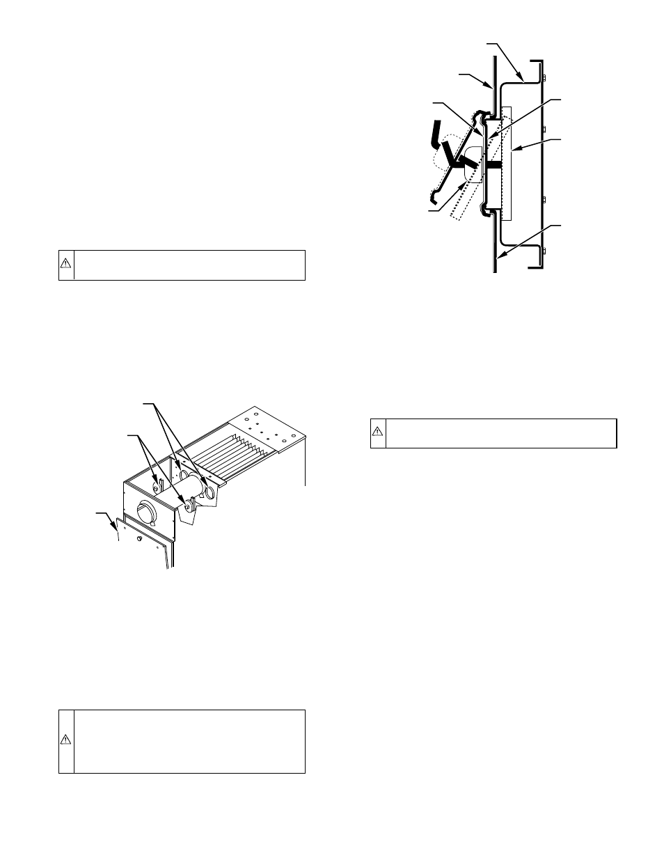
7. Reinstall covers and tighten in place making sure that
covers are properly seated over ports and gasket has sealed
opening. (See Fig. 3.)
WARNING:
Failure to replace cleanout port cover gas-
kets, failure to properly seat covers over ports, and/or
failure to securely tighten wing nuts could lead to flue gas
leakage. This could lead to furnace damage, oil fumes,
sooting, and severe bodily harm.
8. Reconnect flue pipe.
9. Reinstall filter and blower door.
10. Turn on power to unit and readjust burner for proper
operation. Inspect cleanout ports and flue connection to
make sure there are no leaks.
B.
Cleaning Both Primary and Secondary Heat
Exchangers
If a more thorough cleaning is required (both primary and
secondary heat exchanger sections), the following steps should be
performed:
1. Turn off all oil and electrical supplies upstream of furnace.
CAUTION:
If furnace has been in operation, some
surfaces may be hot. Allow time for unit to cool down.
2. Remove blower door.
3. Disconnect flue pipe.
4. Remove outside flue collar.
5. Remove top rear panel.
NOTE:
Blower removal as described in Blower Oiling and
Removal section may be desired for easier access when cleaning
with duct work attached.
6. Remove inside collar on flue pipe.
7. Remove top partition.
8. Place field-fabricated cardboard on metal tray beneath
collector box to prevent debris from entering blower com-
partment.
9. Remove flue collector box from secondary heat exchanger
tube flange. This exposes inside surfaces of secondary tubes
of heat exchanger.
10. Clean secondary tubes and flue pipe with a stiff brush and
vacuum cleaner.
11. Remove louvered door.
12. Disconnect limit control wires.
13. Disconnect oil line and remove oil burner from furnace.
14. Remove observation door and collar on observation tube.
15. Remove intermediate panel. Care must be taken not to bend
or damage limit control.
16. Loosen to hand tightness the 3 nuts labeled "A" in Fig. 4.
Remove screws labeled "B" in Fig. 4. Slide combustion
chamber forward out of heat exchanger. Be careful not to
bump combustion chamber as it becomes brittle after
having been fired.
Fig. 2—Removing Cleanout Port Covers
A96310
CLEANOUT
PORTS
CLEANOUT
PORT COVER
& CLAMP
ASSEMBLY
BLOWER
DOOR
Fig. 3—Reinstalling Cleanout Port Covers
A96311
FLUE BOX
PARTITION
PANEL
CLEANOUT
PORT COVER
WING
CLAMP
NUT
CLEANOUT
COVER
GASKET
CLEANOUT
COVER
CLAMP
BRACKET
INSULATION
—7—
→