Bryant 564B User Manual
Page 16
vacuum cleaner, using a soft brush attachment. Be careful not to
bend the fins. If coated with oil or grease, clean the coils with a
mild detergent-and-water-solution. Rinse coils with clear water,
using a garden hose. Be careful not to splash water on motors,
insulation, wiring or air filter(s). For best results, spray outdoor-
coil fins from inside to outside the unit. On units with an outer and
inner outdoor coil, be sure to clean between the coils. Be sure to
flush all dirt and debris from the unit base.
Inspect the drain pan and condensate drain line when inspecting
the coils. Clean the drain pan and condensate drain by removing all
foreign matter from the pan. Flush the pan and drain tube with
clear water. Do not splash water on the insulation, motor, wiring,
or air filter(s). If the drain tube is restricted, clear it with a
‘‘plumbers snake’’ or similar probe device. Ensure that the
auxiliary drain port above the drain tube is also clear.
V.
OUTDOOR FAN
CAUTION: UNIT OPERATIONAL HAZARD
Failure to follow this caution may result in damage to unit
components.
Keep the Outdoor fan free from all obstructions to ensure
proper cooling operation. Never place articles on top of
the unit.
1. Shut off unit power supply and install lockout tag.
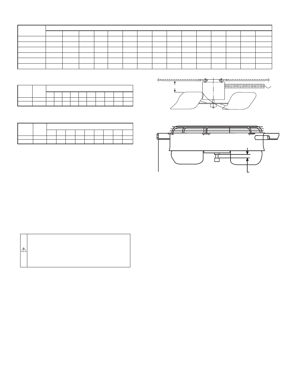
2. Remove outdoor-fan assembly (grille, motor, motor cover,
and fan) by removing screws and flipping assembly onto
unit top cover.
3. Loosen fan hub setscrews.
4. Adjust fan height as shown in Fig. 12 or 13.
5. Tighten setscrews.
6. Replace outdoor-fan assembly.
VI.
ELECTRICAL CONTROLS AND WIRING
Inspect and check the electrical controls and wiring annually. Be
sure to turn off the electrical power to the unit and install lockout
tag.
Remove the top panel to locate all the electrical controls and
wiring. Check all electrical connections for tightness. Tighten all
screw connections. If any smoky or burned connections are
noticed, disassemble the connection, clean all the parts, restrip the
wire end and reassemble the connection properly and securely.
Check to ensure no wires are touching refrigerant tubing or sharp
sheet metal edges. Move and secure wires to isolate from tubing
and sheet metal edges.
After inspecting the electrical controls and wiring, replace all the
panels. Start the unit, and observe at least one complete cooling
cycle to ensure proper operation. If discrepancies are observed in
operating cycle, or if a suspected malfunction has occurred, check
each electrical component with the proper electrical instrumenta-
tion. Refer to the unit wiring label when making these checkouts.
NOTE: Refer to the Sequence of Operation section, as an aid in
determining proper control operation.
VII.
REFRIGERANT CIRCUIT
Inspect all refrigerant tubing connections and the unit base for oil
accumulations annually. Detecting oil generally indicates a refrig-
erant leak.
If oil is detected or if low cooling performance is suspected,
leak-test all refrigerant tubing using an electronic leak-detector, or
liquid-soap solution. If a refrigerant leak is detected, refer to Check
for Refrigerant Leaks section. (See Table of Contents for page
number.)
If no refrigerant leaks are found and low cooling performance is
suspected, refer to Refrigerant Charge. (See Table of Contents for
page number.)
VIII.
INDOOR AIRFLOW
The cooling airflow does not require checking unless improper
performance is suspected. If a problem exists, be sure that all
supply- and return-air grilles are open and free from obstructions,
and that the air filter is clean. When necessary, refer to Indoor
Airflow and Airflow Adjustments section to check the system
airflow.
IX.
METERING DEVICES
Refrigerant cooling metering device is an Accurator (024-042) or
TXV (048 and 060) located upstream of the indoor coil distributor
assembly. Refrigerant heating mode metering device is an Accu-
rater located upstrem of the outdoor coil distributor assembly.
TABLE 9—WET COIL PRESSURE DROP
UNIT SIZE
STANDARD CFM (S.C.F.M.)
600
700
800
900
1000
1100
1200
1300
1400
1500
1600
1700
1800
1900
2000
024
.027
.034
040
.047
.053
-
-
-
-
-
-
-
-
-
-
030
-
.036
.042
.050
.055
.063
.072
.081
-
-
-
-
-
-
-
036
-
-
-
.050
.055
.063
.072
.081
.090
.097
-
-
-
-
-
042
-
-
-
-
.042
.049
.052
.059
.065
.071
.078
.085
.091
-
-
048
-
-
-
-
-
-
.072
.081
.090
.097
.108
.120
.129
.139
-
060
-
-
-
-
-
-
-
-
-
.071
.078
.085
.091
.098
.114
TABLE 10—FILTER PRESSURE DROP (IN. WG)
UNIT
SIZE
FILTER
SIZE
(IN.)
CFM
500 600 700 800 900 1000 1100 1200 1300 1400
024-036 24 x 24 0.06 0.07 0.08 0.08 0.09 0.09 0.09 0.10 0.11 0.12
042-060 30 x 30
-
-
-
-
-
-
-
-
0.08 0.09
UNIT
SIZE
FILTER
SIZE
(IN.)
CFM
1500 1600 1700 1800 1900 2000 2100 2200 2300
024-036 24 x 24 0.14 0.15
-
-
-
-
-
-
-
042-060 30 x 30 0.10 0.11 0.12 0.13 0.14 0.15 0.16 0.17 0.18
Fig. 12—Outdoor-Fan Adjustment (024–048 Size)
C00021
3.125 in.
Fig. 13—Outdoor-Fan Adjustment (060 Size)
C02017
0.708in.
—16—