Burnham V8 Series User Manual
Page 70
70
s
e
h
s
a
l
F
s
m
h
o
n
i
e
c
n
a
t
s
i
s
e
R
ll
e
C
d
a
C
1
0
0
4
n
a
h
t
s
s
e
L
2
0
0
8
n
a
h
t
s
s
e
l
d
n
a
0
0
4
n
a
h
t
e
r
o
M
3
0
0
6
1
n
a
h
t
s
s
e
l
d
n
a
0
0
8
n
a
h
t
e
r
o
M
4
0
0
0
5
n
a
h
t
s
s
e
l
d
n
a
0
0
6
1
n
a
h
t
e
r
o
M
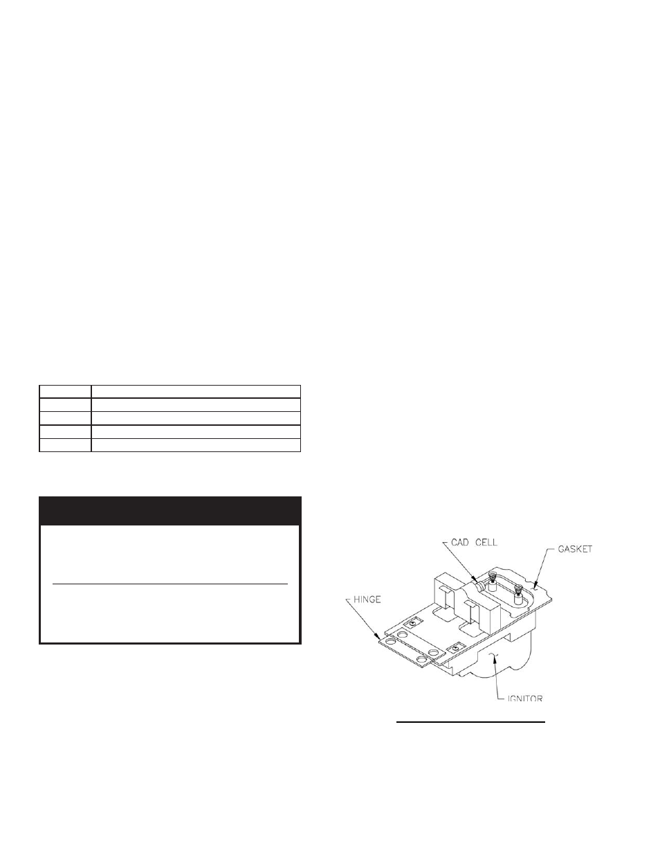
Figure 29: Cad Cell Location
v.
T-T Jumper: Select models have pre-
installed T-T jumper resistor. To remove,
use side-cutting pliers to cut jumper (See
Figure 28).
vi. Diagnostic LED: The indicator light on oil
primary control provides lockout, recycle
and cad cell indications as follows:
•
Flashing at 1 Hz (½ second on, ½ second
off): system is locked out or in Restricted
Mode.
•
Flashing at ¼ Hz (2 seconds on, 2 seconds
off): control is in Recycle Mode.
•
On: cad cell is sensing fl ame.
•
Off: cad cell is not sensing fl ame.
vii. Cad Cell Resistance Check: For proper
operation it is important that the cad cell
resistance is below 1600 ohms. During a
normal call for heat, once the control has
entered the Run Mode, press and release the
reset button. Indicator light will fl ash 1 to 4
fl ashes. See Table 5 for equivalent cad cell
resistance.
TABLE 5: CAD CELL RESISTANCE WHEN
SENSING FLAME
b. CHECK OIL PRIMARY CONTROL
N
O
I
T
U
A
C
e
n
i
l
f
o
d
r
a
z
a
h
l
a
i
t
n
e
t
o
p
e
h
t
o
t
e
u
D
d
e
c
n
e
i
r
e
p
x
e
,
d
e
n
i
a
r
t
a
y
l
n
o
,
e
g
a
t
l
o
v
e
h
t
m
r
o
f
r
e
p
d
l
u
o
h
s
n
a
i
c
i
n
h
c
e
t
e
c
i
v
r
e
s
.
s
k
c
e
h
c
y
t
e
f
a
s
g
n
i
w
o
l
l
o
f
e
l
b
a
e
c
i
v
r
e
s
-
d
l
e
i
f
o
n
s
n
i
a
t
n
o
c
l
o
r
t
n
o
c
s
i
h
T
.
t
r
a
p
a
t
i
e
k
a
t
o
t
t
p
m
e
t
t
a
t
o
n
o
D
.
s
t
r
a
p
t
o
n
s
i
n
o
i
t
a
r
e
p
o
f
i
l
o
r
t
n
o
c
e
r
i
t
n
e
e
c
a
l
p
e
R
.
d
e
b
i
r
c
s
e
d
s
a
i.
Preliminary Steps
•
Check wiring connections and power
supply.
•
Make sure power is on to the controls.
•
Make sure limit control is closed.
•
Check contacts between ignitor and the
electrodes.
•
Check the oil pump pressure.
•
Check the piping to the oil tank.
•
Check the oil nozzle, oil supply and oil
fi lter.
ii. Check Safety Features
Safe
Start:
•
Place a jumper across cad cell terminals.
•
Follow procedure to turn on burner.
Burner must not start, indicator light turns
on and control remains in Idle Mode.
•
Remove jumper.
iii. Simulate Ignition or Flame Failure:
•
Follow procedure to turn on burner.
•
Close hand valve in oil supply line.
•
Failure occurs, device enters Recycle
Mode. Indicator light fl ashes at ¼ Hz rate
2 seconds on, 2 seconds off).
•
Device tries to restart system after
approximately 60 seconds.
•
After third Recycle Mode trial, safety
switch locks out within safety switch
timing indicated on label and control
enters Restricted Mode. Indicator light
fl ashes at 1 Hz rate (½ second on, ½
second off). Ignition and motor stop and
oil valves closes.
•
To reset from Restricted Mode: Press and
hold the reset button for 30 seconds.
When
the
LED
fl ashes twice, the device
has
reset.
iv. Cad Cell Check: See Figure 29.