Burnham V8 Series User Manual
Page 67
67
b. Locate oil pressure adjusting screw and turn
screw to obtain proper pump pressure, refer to
Table 6 at rear of manual.
c. To check the cutoff pressure, deadhead a reliable
pressure gauge onto the copper connector tube
attached to the nozzle port. Run the burner for
a short period of time. Shut the burner off. The
pressure should drop and hold.
d. Remove the gauge and install bleeder port and/or
reconnect the nozzle port line.
G. ADJUST OIL BURNER WHILE OPERATING.
(fl ame present)
1. ADJUST DRAFT REGULATOR for a draft of
— .02” (water gauge) over the fi re after chimney has
reached operating temperature and while burner is
running.
2. READJUST THE AIR BAND on burner for
a light orange colored fl ame while the draft over
the fi re is —.02”. Use a smoke tester and adjust
air for minimum smoke (not to exceed #1) with a
minimum of excess air. Make fi nal check using
suitable instrumentation to obtain a CO
2
of 11.5 to
12.5% with draft of —.02” (water gauge) in fi re
box. These settings will assure a safe and effi cient
operating condition. If the fl ame appears stringy
instead of a solid fi re, try another nozzle of the same
type. Flame should be solid and compact. After all
adjustments are made recheck for a draft of —.02”
over the fi re.
3. READJUST THE HEAD SETTING only if
necessary.
Beckett Burners
a. V82 & V83:
Beckett MB(L1) Head burners have a fi xed head
which are non-adjustable.
b. V84 thru V89:
Beckett MD(V1) (variable) Head burners have
the ability to control air by moving the head. It
might be necessary to move the head forward
or back one position at a time to optimize the
smoke and CO
2
readings. See Figure 27A.
Carlin 102CRD Burners
a. V87 through V89
The Carlin 102 CRD-3 Burner has the ability
to control air by moving the head. It might be
necessary to move the head forward or back one
position at a time to optimize the smoke and
CO2 readings.
b. If the fi re is a little too rich, move the
combustion head slightly forward by increasing
dimension “A”. Refer to Figure 27B.
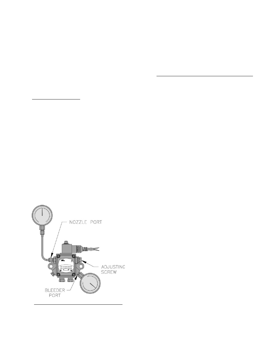
Figure 26: Adjusting Fuel Pump Pressure
2) change the factory air settings according to
Table 6 and,
3) check the oil pump pressure and adjust if
necessary to the setting specifi ed in Table 6,
refer to Paragraph F for details.
5. Riello Burners
a. OPEN ALL OIL LINE VALVES.
b. Provide a pan to catch oil.
c. Remove pressure port/bleeder plug from fuel
pump and install Riello Combination Pressure
Gauge and Bleeder Valve Assembly.
d. OPEN FLAME OBSERVATION PORT COVER
on burner swing door.
F. START OIL BURNER.
1. Open vent fi tting on fuel pump.
2. TURN ‘ON’ BURNER service switch and
allow burner to run until oil fl ows from vent
fi tting in a SOLID stream without air bubbles for
approximately 10 seconds.
3. Close vent fi tting and burner fl ame should start
immediately after prepurge is completed. Prepurge
prevents burner fl ame until 10 seconds has elapsed
after initial power is applied to burner. During
prepurge the motor and igniter will operate but the
oil valve will remain closed. Refer to Oil Primary
Control Instructions for more details.
4. Adjust oil pressure.
a. When checking a fuel unit's operating pressure, a
reliable pressure gauge may be installed in either
the bleeder port or the nozzle port. See Figure
26.