Burnham V8 Series User Manual
Page 20
20
i.
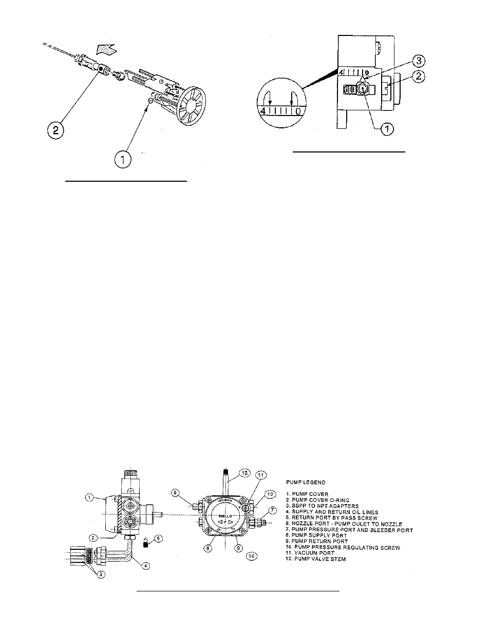
Remove the nozzle adapter (2) from the
drawer assembly by loosening the screw (1).
ii. Remove existing nozzle from nozzle
adapter.
iii. Insert the proper nozzle into nozzle adapter
and tighten securely (Do not over tighten).
iv. Replace adapter, with nozzle installed, into
drawer assembly and secure with screw (1).
c. Inspect and measure burner electrodes. Refer to
Figure 27D for the proper electrode settings.
d. Re-install Drawer Assembly into Comustion
Head per Step 7c above.
e. Insertion Depth, verify the distance between
the tip of the end cone is equal to the distance
specifi ed in Table 6 of this manual.
f. Turbulator Setting, refer to Figure 7D.
i. Confi rm the turbulator setting is correct
for standard higher (maximum) input
oil nozzle installed in the burner. If the
lower (minimum) input is desired, readjust
turbulator setting to index mark specifi ed in
Table 6 of this manual.
ii. Loosen nut (1) and turn screw (2) until the
index marker (3) is aligned with the correct
index number in the Burner Setup Chart
(Table 6).
iii. Retighten the retaining nut (1).
MODEL F3 NOTE: Zero and three are scale
indicators only. From left to right the fi rst line is
3 and the last line 0.
MODEL F5: Same as above, except, scale
indicators are 0 and 4.
MODEL F10: Same as above, except, scale
indicators are 0 and 5.
i.
Pump Connections and Port Identifi cation,
refer to Figure 7E.
This burner is shipped with the oil pump
set to operate on a single line system. To
operate on a two-line system the bypass
plug must be installed.
WARNING: Do not operate a single line system
with the by-pass plug installed. Operating a
single line system with the by-pass plug installed
will result in damage to the pump shaft seal.
NOTE: Pump pressure was factory pre-set but
must be checked at time of burner start-up. A
pressure gauge is attached to the PRESSURE/
BLEEDER PORT (7) for pressure readings. Two
PIPE CONNECTORS (4) are supplied with the
burner for connection to either a single or two-
line system. Also supplied are two ADAPTORS
(3), two female ¼” NPT to adapt oil lines to
burner pipe connectors. All pump port threads
are British Parallel Thread design. Direct
connection of NPT threads to the pump will
damage the pump body.
Figure 7C: Nozzle Replacement
Figure 7D: Turbulator Setting
Figure 7E: Pump Connections and Port Identifi cation