Table 1 — physical data (cont) – Bryant DURAPAC 580F User Manual
Page 9
—
9
—
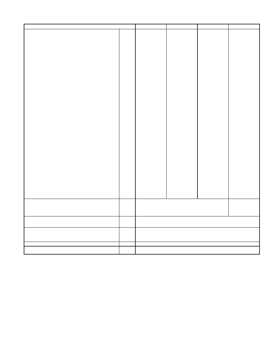
Table 1 — Physical Data (cont)
LEGEND
*Evaporator coil fin material/condenser coil fin material. Contact your local rep-
resentative for details about coated fins.
†Weight of 14-in. roof curb.
**Single phase/three-phase.
††Rollout switch lockout is manually reset by interrupting power to unit or reset-
ting thermostat.
||California rated three-phase high heat models.
***Three phase standard high-heat models have heating input values as shown.
Single phase standard high heat models have one-stage heating with heating
input values as follows:
580FJV036115 — 115,000 Btuh
580FJV048150 — 150,000 Btuh
580FJV060150 — 150,000 Btuh
†††California SCAQMD compliant Low NO
x
models have combustion products
that are controlled to 40 nanograms per joule or less.
580F UNIT SIZE
036
048
060
072 AND 073
FURNACE SECTION
Rollout Switch Cutout
Temp (F)††
195
195
195
195
Burner Orifice Diameter
(in. ...drill size)
Natural Gas
Std
074
.113...33
.113...33
.113...33
.113...33
114/115
.113...33
.113...33
.113...33
.113...33
149/150
—
.129...30
.129...30
.129...30
060N
.102...38
.102...38
.102...38
—
090N
.102...38
.102...38
.102...38
—
120N
—
.116...32
.116...32
—
Liquid Propane
Alt
074
.089...43
.089...43
.089...43
.089...43
114/115
.089...43
.089...43
.089...43
.089...43
149/150
—
.104...37
.104...37
.104...37
060N
.082...45
.082...45
.082...45
—
090N
.082...45
.082...45
.082...45
—
120N
—
.094...42
.094...42
—
Thermostat Heat Anticipator
Setting (amps)
208/230 v and 575
Stage 1
.14
.14
.14
.14
Stage 2
.14
.14
.14
.14
460 v
Stage 1
.14
.14
.14
.14
Stage 2
.14
.14
.14
.14
Gas Input (Btuh)
CA High Output 3-Phase Units
114||
115,000
—
—
—
149||
—
150,000
150,000
—
Standard Units
074
74,000/—
74,000/—
74,000/—
74,000/—
(Stage 2/ Stage 1)
115***
115,000/82,000
115,000/—
115,000/—
115,000/—
150***
—
150,000/120,000
150,000/120,000
150,000/120,000
Low NOx Units
060N†††
60,000
60,000
60,000
—
090N†††
90,000
90,000
90,000
—
120N†††
—
120,000
120,000
—
Efficiency (Steady
State) (%)
80
80
80
80
Temperature Rise Range
074
25-55
25-55
25-55
25-55
114/115
55-85
35-65
35-65
35-65
149/150
—
50-80
50-80
50-80
060N
20-50
20-50
20-50
—
090N
30-60
30-60
30-60
—
120N
—
40-70
40-70
—
Manifold Pressure (in. wg)
Natural Gas
Std
3.5
3.5
3.5
3.5
Liquid Propane
Alt
3.5
3.5
3.5
3.5
Gas Valve Quantity
1
1
1
1
Gas Valve Pressure Range
Psig
0.180-0.487
0.180-0.487
0.180-0.487
0.180-0.487
in. wg
5.0-13.5
5.0-13.5
5.0-13.5
5.0-13.5
Field Gas Connection
Size (in.)
1
/
2
1
/
2
1
/
2
1
/
2
HIGH-PRESSURE SWITCH (psig)
Standard Compressor
450 ± 50
500 ± 50
Internal Relief (Differential)
Cutout
428
428
Reset (Auto.)
320
320
LOSS-OF-CHARGE (LOW-PRESSURE SWITCH) (psig)
Cutout
7 ± 3
Reset (Auto.)
22 ± 7
FREEZE PROTECTION
THERMOSTAT (F)
Opens
30 ± 5
Closes
45 ± 5
OUTDOOR-AIR INLET SCREENS
Cleanable. Screen size and quantity varies with option selected.
RETURN-AIR FILTERS
Throwaway
Quantity...Size (in.)
2...16 x 25 x 2
Al
—
Aluminum
Bhp —
Brake Horsepower
Cu
—
Copper