Bryant DURAPAC 580F User Manual
Page 42
—
42
—
Table 34 — LED Error Code Description*
LEGEND
LED — Light-Emitting Diode
*A 3-second pause exists between LED error code flashes. If more
than one error code exists, all applicable codes will be displayed in
numerical sequence.
†Indicates a code that is not an error. The unit will continue to operate
when this code is displayed.
IMPORTANT: Refer to Troubleshooting Tables 35-37 for additional infor-
mation.
XII. MAIN BURNERS
To access burners, remove burner access panel and slide out
burner partition. At the beginning of each heating season,
inspect for deterioration or blockage due to corrosion or other
causes. Observe the main burner flames and adjust, if
necessary.
A. Removal and Replacement of Gas Train (Fig. 44-46)
1. Shut off manual gas valve.
2. Shut off power to unit and tag disconnect.
3. Slide out burner partition.
4. Disconnect gas piping at unit gas valve.
5. Remove wires connected to gas valve. Mark each
wire.
6. Remove ignitor wires and sensor wires at the Inte-
grated Gas Unit Controller (IGC) (see Fig. 11).
7. Remove the 2 screws that attach the burner rack to
the vestibule plate (Fig. 44).
8. Slide the burner tray out of the unit (Fig. 45).
9. To reinstall, reverse the procedure outlined above.
B. Cleaning and Adjustment
1. Remove burner rack from unit as described in
Removal and Replacement of Gas Train section, above.
2. Inspect burners; if dirty, remove burners from rack.
3. Using a soft brush clean burners and cross-over port
as required.
4. Adjust spark gap. See Fig. 46.
5. Reinstall burners on rack.
6. Reinstall burner rack as described in Removal and
Replacement of Gas Train section, above.
XIII. HIGH-PRESSURE SWITCH
Located on the compressor hot gas line is a high-pressure
switch containing a Schrader core depressor. This switch
opens at 428 psig and closes at 320 psig. No adjustment is
necessary. Refer to Table 1.
XIV. LOSS OF CHARGE SWITCH
Located on the condenser liquid line is a low-pressure switch
which functions as a loss-of-charge switch. This switch con-
tains a Schrader core depressor. This switch opens at 7 psig
and closes at 22 psig. No adjustment is necessary. Refer to
Table 1.
XV. FREEZESTAT
Located on the “hair pin” end of the evaporator coil is a
bimetal temperature sensing switch. This switch protects
the evaporator coil from freeze-up due to lack of airflow. The
switch opens at 30 F and closes at 45 F. No adjustment is
necessary. Refer to Table 1.
XVI. REPLACEMENT PARTS
A complete list of replacement parts may be obtained from
any Bryant distributor upon request.
LED INDICATION
ERROR CODE DESCRIPTION
ON
Normal Operation
OFF
Hardware Failure
1 Flash†
Evaporator Fan On/Off Delay Modified
2 Flashes
Limit Switch Fault
3 Flashes
Flame Sense Fault
4 Flashes
4 Consecutive Limit Switch Faults
5 Flashes
Ignition Lockout Fault
6 Flashes
Induced-Draft Motor Fault
7 Flashes
Rollout Switch Fault
8 Flashes
Internal Control Fault
9 Flashes
Internal Software Processor Fault
CAUTION: When working on gas train, do not hit or
plug orifice spuds.
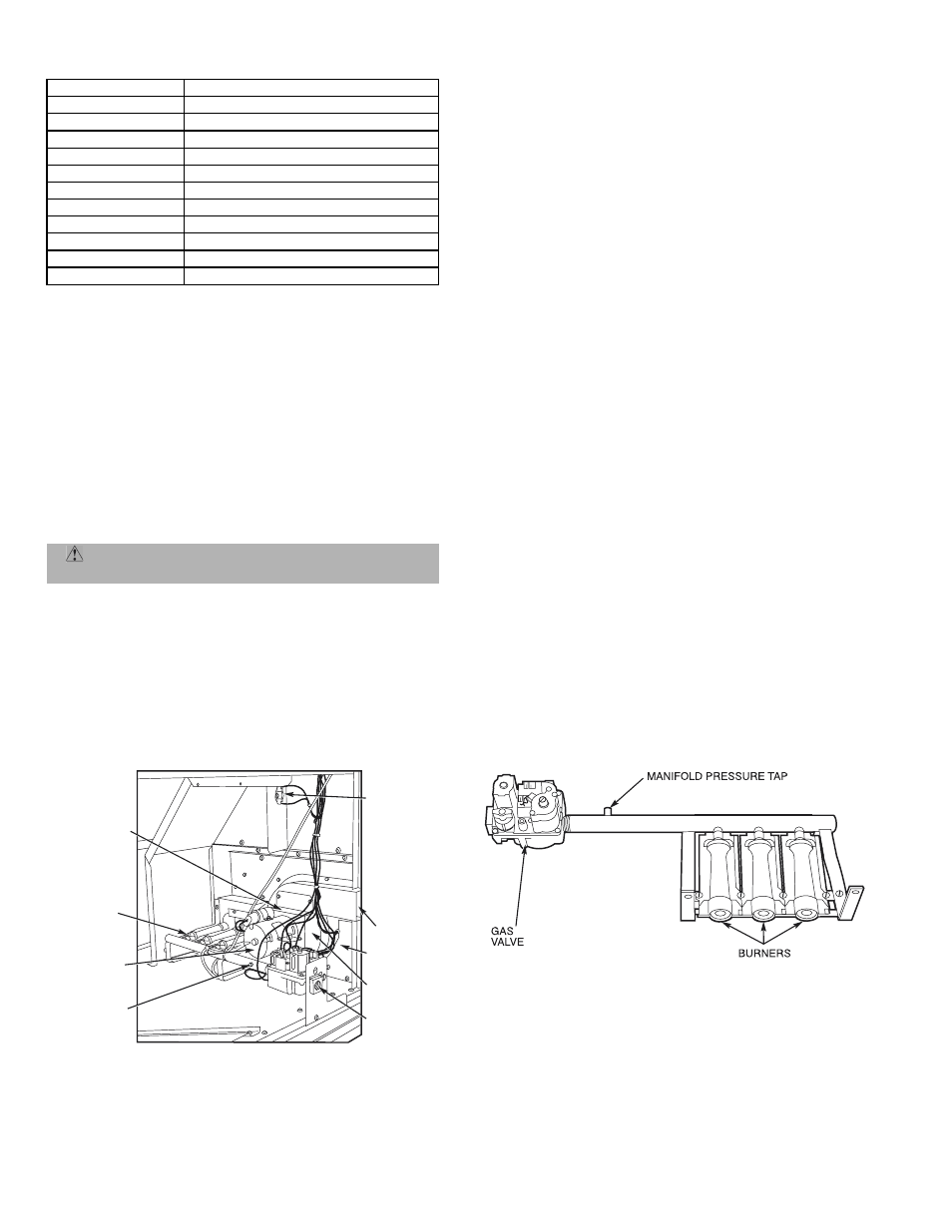
Fig. 45 — Burner Tray Details
INDUCED-
DRAFT
MOTOR
MOUNTING
PLATE
INDUCED-
DRAFT
MOTOR
MANIFOLD
PRESSURE
TAP
VESTIBULE
PLATE
FLUE
EXHAUST
ROLLOUT
SWITCH
BLOWER
HOUSING
GAS
VALVE
BURNER
SECTION
Fig. 44 — Burner Section Details