Controls and indicators – American Power Conversion MX28B200 User Manual
Page 54
Page 48 MX28B200/400 –48 VDC User’s Manual (990-9133)
Rated Output Power (per Rectifier)
2800 W (45ºC)
Efficiency
91% Typical
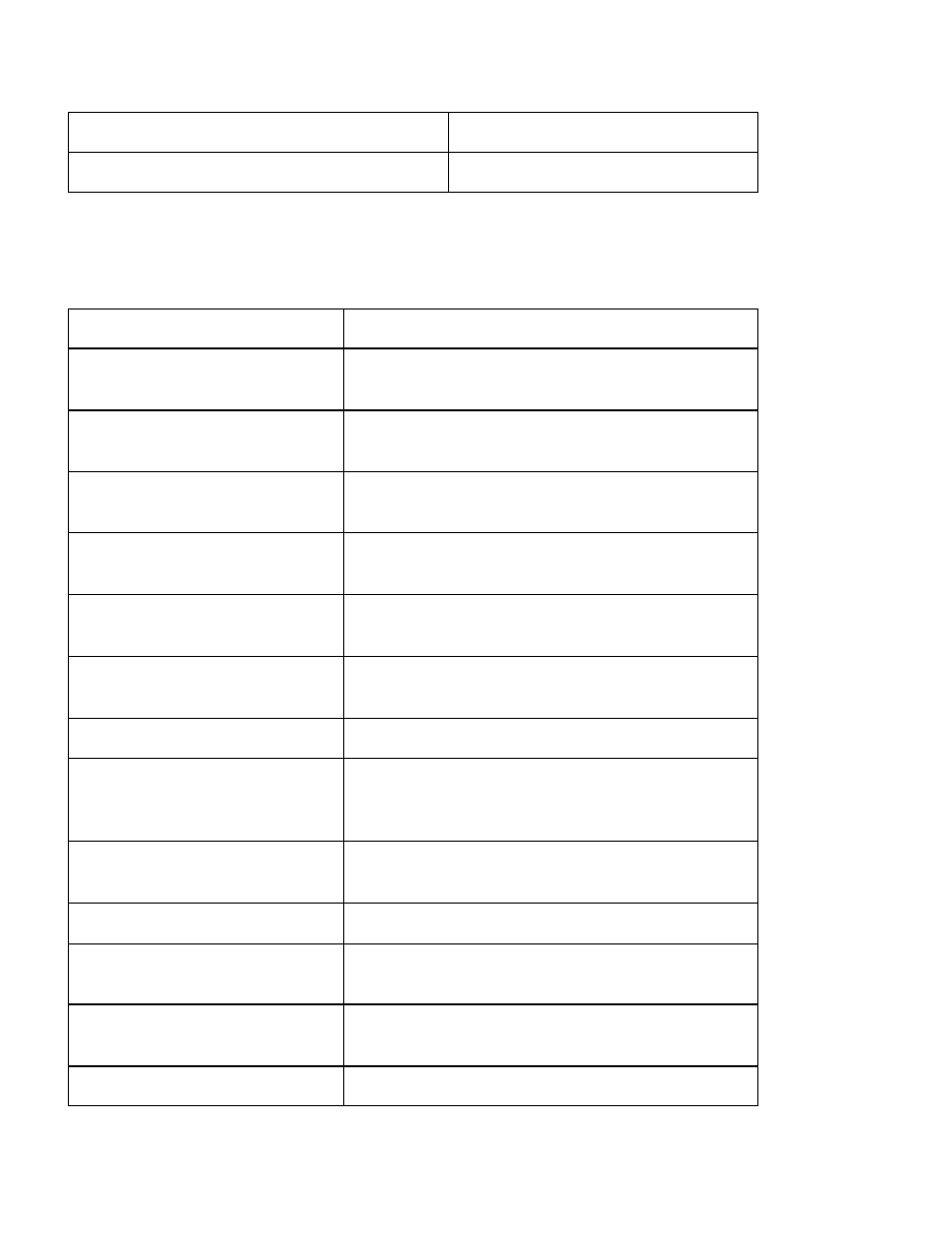
6.3. Controls and Indicators
Rectifiers
Input Healthy LED
AC power present.
Output Healthy LED
DC output voltage within operating range (-39.5
to –59.5 VDC).
Output Current LED
On when rectifier is supplying current.
Thermal Control LED
On when one of three internal sensors is above
90ºC
Current Limit LED
On when rectifier is in current limit.
.
Overvolts LED
On when rectifier is above 57 Volts. (Must be
powered down to reset)
Overtemp LED
On when one of three internal sensors is above
130ºC. Power Conversion is inhibited.
Fan fail LED
On when Fan is running too slow.
Standby LED
On when the unit is in the standby mode. No
output power is produced. Rectifier is still
active
+V Test Point
Rectifier Voltage can be measured with a
voltmeter between COM and +V.
COM Test Point
Negative reference for both +V and +I
+I Test Point
Rectifier Current can be measured with a
voltmeter between COM and +I.
Float / Boost/Equalize Switch
Used to Control voltage on systems without a
PSCU
Float Trim Pot
The float pot is used to adjust the default float