Agri-Fab 45-0325 User Manual
Page 7
7
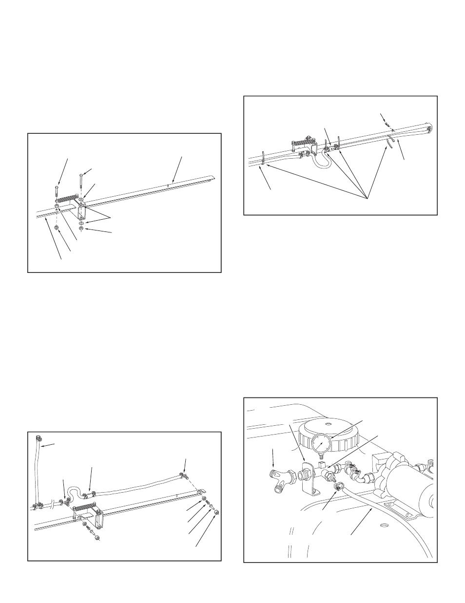
FIGURE 12
24. Tie the hoses to the
front of the boom using four nylon
ties per side as shown in the
front view in fi gure 13.
After tightening, cut excess length off ends of ties .
25. Insert a 3/32" hair cotter pin into the welded pin at each
end of the boom. These pins will be used to lock the
boom arm to the transport bracket when the arm is in
the folded position. See fi gure 13.
19. Attach the (RH) boom arm assembly to the (RH) boom
mount assembly as shown in fi gure 11, using a 3/8" x
4-1/4" hex bolt, three 3/8" fl at washers, and one 3/8"
nylock nut. Do not overtighten.
20. Place a 3/8" x 2-1/2" hex bolt through the loose end of
the spring and then assemble a 3/8" plain hex nut onto
the bolt. Fasten the hex bolt to the boom mount assembly
using a 3/8" nylock nut.
Tighten the nuts, exposing one
or two threads on the end of the bolt. See fi gure 11.
21. Repeat steps 19 and 20 for the (LH) boom arm
assembly.
22. Attach the hose assembly to the
front of the boom, with
the nozzles pointing to the rear. Remove the nozzle nut,
nozzle, strainer screen and elbow nut, from the elbow
fi ttings and place the elbow through the hole at the end
of the boom arm. Secure it using the plastic elbow nut.
Insert the strainer screen and then assemble the spray
nozzle and the nozzle nut, keeping the nozzle opening
facing down while tightening. See fi gure 12.
23. Attach the hose assembly tee fi ttings to the boom using
the same procedure as was used for the elbows. See
fi gure 12.
(RH) SIDE VIEWED FROM REAR
(RH) SIDE VIEWED FROM REAR
FIGURE 11
FIGURE 13
VIEWED FROM FRONT
FIGURE 14
NOTE: To help prevent leaking, use thread tape when
assembling the "Y" valve fi tting and the pressure gauge in
the following paragraphs.
26. Carefully screw the "Y" valve fi tting onto the fi tting
attached to the tee support bracket. The valve levers
should face up. See fi gure 14.
27. Carefully screw the pressure gauge into the top of the
tee fi tting as shown in fi gure 14.
28. Place the 1/4" hose clamp over the end of the spray gun
hose. Push the hose onto the hose barb on the front
of the tee fi tting. Secure the hose to the barb with the
hose clamp. See fi gure 14.
NOZZLE NUT
SPRAY NOZZLE
STRAINER SCREEN
ELBOW NUT
ELBOW
ON-OFF VALVE
TEE
BOOM CONNECTING HOSE
NYLON TIES
3/32" HAIR COTTER PIN
ON-OFF VALVE
TIE TO FRONT
OF BOOM
TIE TO
FRONT OF
BOOM
COILED HOSE
CLAMP
SPRAY GUN HOSE
20
40
60
80
100
0
PRESSURE
GAUGE
TEE FITTING
"Y" VALVE
TEE SUPPORT
BRACKET
(RH) BOOM
ARM ASSEMBLY
3/8" FLAT WASHER
3/8" NYLOCK NUT
3/8" x 4-1/4" HEX BOLT
3/8" FLAT WASHER
3/8" x 2-1/2"
HEX BOLT
(RH) BOOM MOUNT ASSEMBLY
3/8" NYLOCK NUT
3/8" PLAIN HEX NUT