Agri-Fab 45-0325 User Manual
Page 6
6
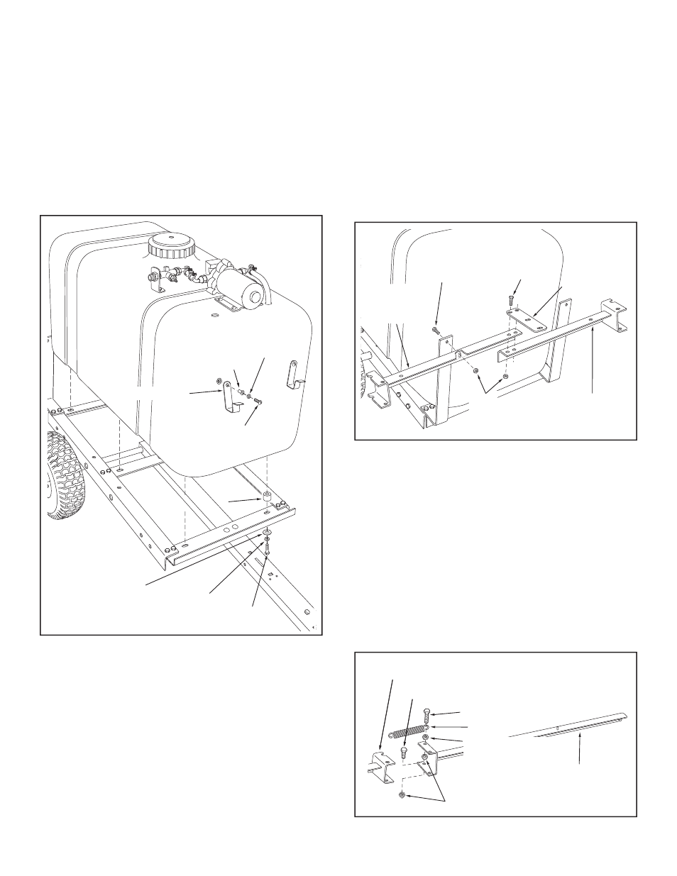
11. Attach the tank to the frame using six 1/2" spacers with
six 3/8" x 1-1/4" hex bolts, 3/8" lock washers and 3/8"
fl at washers. Place the spacers between the tank and
the frame.
Tighten the six bolts until the lock washers
are fl attened. See fi gure 8.
12. Assemble the hose hooks to the front of the tank using
two #10-24 x 1/2" screws, two 3/16" lock washers and
two fl anged spacers.
Tighten the screws until the lock
washers are fl attened. See fi gure 8.
IMPORTANT: Do not overtighten bolts fastening to tank.
Tighten until lock washers are snug and fl attened.
FIGURE 10
13.
Tighten securely the 12 bolts and nuts fastening the
frame strap and the front and rear angles to the side
angles. (Figures 1 and 2)
Tighten only until snug the 2 bolts and nuts fastening
the axle to the frame. (Figure 4)
Tighten securely the 4 nuts fastening the tongue to the
frame. (Figure 3)
FIGURE 8
14. Assemble the (RH) and (LH) boom mount assemblies
to the boom mount brackets using two 5/16" x 3/4" hex
bolts and 5/16" nylock nuts. Fasten through the slotted
hole in each boom mount assembly.
Do not tighten
yet. See fi gure 9.
15. Align the holes in the boom transport bracket with the
holes in the ends of the boom mount assemblies as
shown in fi gure 9. Fasten them together using two 5/16"
x 1" hex bolts and 5/16" nylock nuts.
Tighten the bolts
assembled in this step and in step 14.
NOTE: If the holes in the boom mount assemblies won’t
line up, temporarily loosen the bolts which fasten the boom
mount brackets to the frame.
16. Assemble a 3/8" x 3/4" hex bolt and 3/8" nylock nut to
the hole shown in the bottom of the welded bracket
on the (RH) boom arm assembly.
Tighten. See fi gure
10.
17. Assemble a spring and a 3/8" plain hex nut onto a 3/8"
x 1-1/4" hex bolt. Fasten the bolt to the hole shown in
the top of the welded bracket using a 3/8" nylock nut.
Tighten so that the nylock nut is even with the end of
the bolt. See fi gure 10.
18. Repeat steps 16 and 17 for the (LH) boom arm
assembly.
FIGURE 9
VIEWED FROM REAR
(RH) SIDE VIEWED FROM REAR
1/2" SPACER
3/8" FLAT
WASHER
3/8" LOCK
WASHER
3/8" x 1-1/4"
HEX BOLT
HOSE HOOK
FLANGED
SPACER
3/16" LOCK
WASHER
#10-24 x 1/2"
SCREW
5/16" x 3/4"
HEX BOLT
5/16" x 1"
HEX BOLT
5/16"
NYLOCK
NUTS
(LH) BOOM
MOUNT
ASSEMBLY
BOOM
TRANSPORT
BRACKET
(RH) BOOM
MOUNT
ASSEMBLY
3/8" x 1-1/4" HEX BOLT
3/8" NYLOCK NUT
3/8" x 3/4" HEX BOLT
3/8" PLAIN HEX NUT
SPRING
(RH) BOOM
ARM ASSEMBLY
(RH) BOOM
MOUNT ASSEMBLY