Vent pipe installation, Vent pipe length – American Water Heater Power Flex 40-42K BTU User Manual
Page 8
8
Vent Pipe Installation
The following guidelines should be followed when installing
the air inlet and exhaust outlet piping:
•
Venting should be as direct as possible with a
minimum number of pipe fittings.
•
Vent diameter must not be reduced unless
specifically noted in the installation instructions.
•
Support all horizontal pipe runs every four feet
and all vertical pipe runs every six feet or
according to local codes.
•
Vents run through unconditioned spaces where below
freezing temperatures are expected should be prop-
erly insulated to prevent freezing. For horizontal runs,
wrap the vent pipe with self-regulating 3 or 5 watt heat
tape. The heat tape must be U.L. listed and installed
per the manufacturer’s instructions.
•
Do not connect this venting system with an existing
vent or chimney.
•
Do not common vent with the vent pipe of any other
water heater or appliance.
The combustion air inlet and exhaust outlet piping and
termination may be installed in one of the following type
terminations:
1. Standard Horizontal (2 Pipe)
2. Vertical (2 Pipe)
3. Concentric Vent - Through the Wall
All pipe, fittings, pipe cement, primers and procedures
must conform to American National Standard Institute and
American Society for Testing and Materials (ANSI/ASTM)
standards in the United States. This water heater has been
design certified by CSA International for use with the listed
plastic vent pipe material.
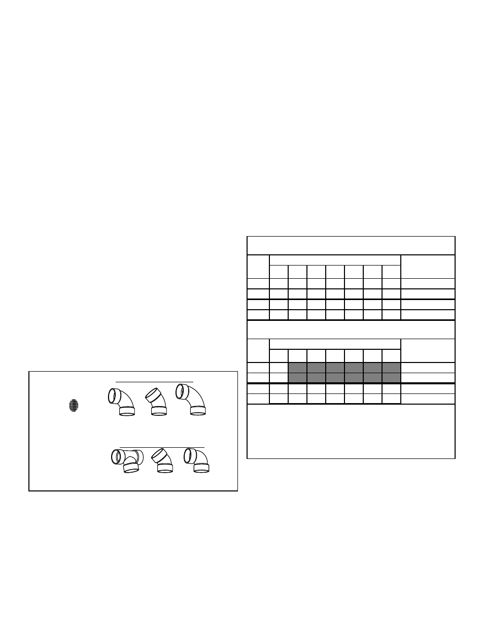
IMPORTANT: Do not use vent elbows in this vent pipe
installation (see figure 3 below).
Note: It is important to select the proper pipe cement
for the type plastic pipe being used.
3. Assemble the parts quickly while the cement is still
wet. Twist the pipe 1/4 turn during insertion and hold
for 30 seconds.
Vent Pipe Length
Size the exhaust outlet and combustion air inlet pipes as
specified in Table 3 below. This table lists the maximum
allowable length in feet of the exhaust outlet and combus-
tion air inlet pipes as related to the number of required
elbows and the termination. The specified maximum
lengths are for the separate inlet and exhaust pipe systems
and not the combined length of both systems. Minimum
pipe length is 3 feet with one elbow per side.
1. Determine termination type and pipe size.
2. Determine number of elbows in exhaust pipe (Do not
include elbows in the termination.) Corresponding
number indicates the maximum length of exhaust pipe.
3. Determine number of elbows in inlet pipe. (Do not
include elbows in the termination.) The corresponding
number indicates the maximum length of inlet pipe.
All joints in the inlet and outlet piping must be properly
cemented. Size and cut all piping before cementing.
1. Cut the pipe end square and remove all ragged edges
and burrs. Make sure the inside of the pipe is clean
and free of cuttings and loose dirt. Chamfer the end
and apply primer to the fitting and pipe.
2. Using a suitable grade of pipe cement, apply a moder-
ate, even coat inside the fitting. Apply a liberal amount
of cement to the outside of the pipe to socket depth.
CORRECT FITTINGS
Mesh Metal
Rodent Screen
90° Medium
Sweep Elbow
45° Sweep
Elbow
90° Long
Sweep Elbow
INCORRECT FITTINGS
90° Vent
Elbow
45° Vent
Elbow
Tee Connector
Figure 3
Correct and Incorrect
Pipe Fittings
Table 3 - Maximum Allowable Length in Feet of Exhaust and
Inlet Air Pipe - (42K BTU/Hr models only)
Pipe
Size
(in)
Number of 90° Elbows (medium or long sweep only)
Termination
Options
0
1
2
3
4
5
6
2
40
35
30
25
20
15
10
Std. Horizontal
2
40
35
30
25
20
15
10
Vertical
3
120
115
110
105
100
95
90
Std. Horizontal
3
115
110
105
100
95
90
85
Vertical
Table 4 - Maximum Allowable Length in Feet of Exhaust and
Inlet Air Pipe - (50K/60K BTU/Hr models only)
Pipe
Size
(in)
Number of 90° Elbows (medium or long sweep only)
Termination
Options
0
1
2
3
4
5
6
2
N/A
Std. Horizontal
2
N/A
Vertical
3
45
40
35
30
25
20
15
Std. Horizontal
3
55
50
45
40
35
30
25
Vertical
NOTE:s:
1. N/A - Not Applicable
2. The above maximum lengths are for outlet pipe systems.
3. Maximum of 6 elbows may be used. Use only medium or long
sweep elbows. See figure 8 for details.
4. Two 45° elbows are considered equivalent to one 90° elbow.
5. Minimum length is 3 foot with 1 elbow.
6. Use schedule 40 or 80 CPVC, 40 ABS, or 40 PVC pipe and fittings.